This is a work in progress but, there is plenty of very useful code and information here. With the motor controller and Arduino code in this article you should be able to produce a remote controlled car that drives and turns using two drive motors. One on the left and one on the right.
My end goal is to use a motorized wheelchair and convert it to use tracked tread and haul loads of up to 300 pounds.
For now I have just been playing with a seeedstudio motor controller to control two hobby motors on an Arduino mega. I went with the mega due to spi pin constraints. Since I am using the nrf24 as the wireless interface, I was unable to use the motor controller and the nrf24 on the Uno since they both required the use of the same pins. The mega allows for the use of both modules and still leaves plenty of extra I/O for future expansion. On the transmitter side, I am using an Uno, a joystick shield and an nrf24.
There are a couple of important notes to make when working with the nrf24. First and most importantly, is that they can only be powered by 3.3 volts. If you try to power them with 5 volts you will fry them. Second, is that they have higher peak power requirements than the Arduino boards can supply. If you want to power them from the Arduino, you will need to add a 10uf – 100uf capacitor from power to ground on the nrf24 modules ( pins 1 & 2 ). Make sure you have the capacitor polorized with the ground of the capacitor going to the ground ( pin 1 ) of the nrf24 module.
Also, I would like to mention that I had a great deal of help from gpop1 in the Arduino forums on this. He had a great attitude and helped me clean the code up and make it much more readable and efficient. Without him I would have working but slow and messy code. Thanks gpop1!
Items used for this project
- Arduino Mega 2560
- Arduino Uno
- Joystick Shield
- Seeedstudio Motor Controller
- 2 Hobby Motors
- 2 100uf Capacitors
Tools used in this project
- Soldering iron
- Wire stripper/cutter
NRF24 Versions, and Ranges
Amplified Version The amplified version hooks up the same but, I would not suggest running it using the 3.3 volts from the Arduino. The module is already using all the power it can from the Arduino without being amplified. If you decide that you need or want the amplified version, then you need to consider how you are going to power it.
Low Powered Version If you are going to continue to use the non amplified version, you can add a single piece of cat5 wire that is 83.33 mm (3.279528 inches) long to it to extend the range by as much as 60 meters. Without the extra length of wire you will only get about 15 meters out of it. Here is a video explaining the antenna mod. Antenna Mod Video
Choosing a power source
Considerations
- Maximum sustainable voltage the motors can take
- Is your voltage within the acceptable input range for the Arduino
- Is your voltage within the acceptable input range for the motor controller
- How long do you want to be able to use it for
- How is the battery weight going to effect your performance and run time
For the car: I would suggest something like you find in most hobby cars. Typically 7.2 or 9.6 volt battery pack with a charger. From there you can pigtail right off of the input to the motor controller with a standard barrel plug for the Arduino.( NOTE: this is only if you have bought a quality motor shield or used the one I outlined earlier in the post since they have protection circuitry built in to protect from voltage spikes that come from the motors.)
For the controller: I would suggest using a large booster battery like the ones for cell phones. I found some at the 5 and Below Store for $5 that are 6600 ma and is capable of an output of 5 volts at 1 amp. It already has the necessary circuitry for charging all you need is a cell phone charger and cable to charge it. Then, just use a standard USB cable and plug it into your Arduino controller. Very convenient.
Connections
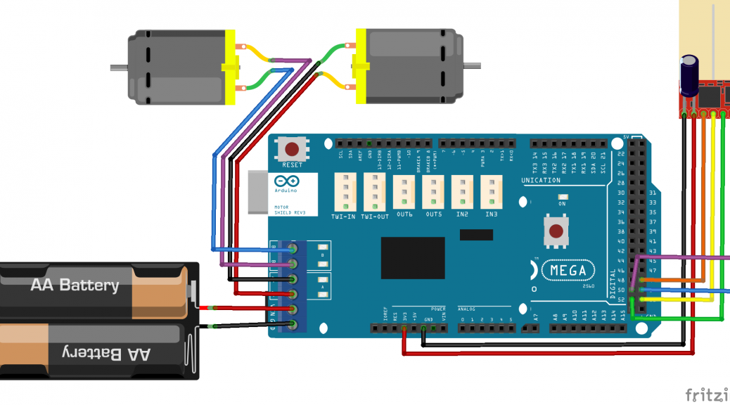
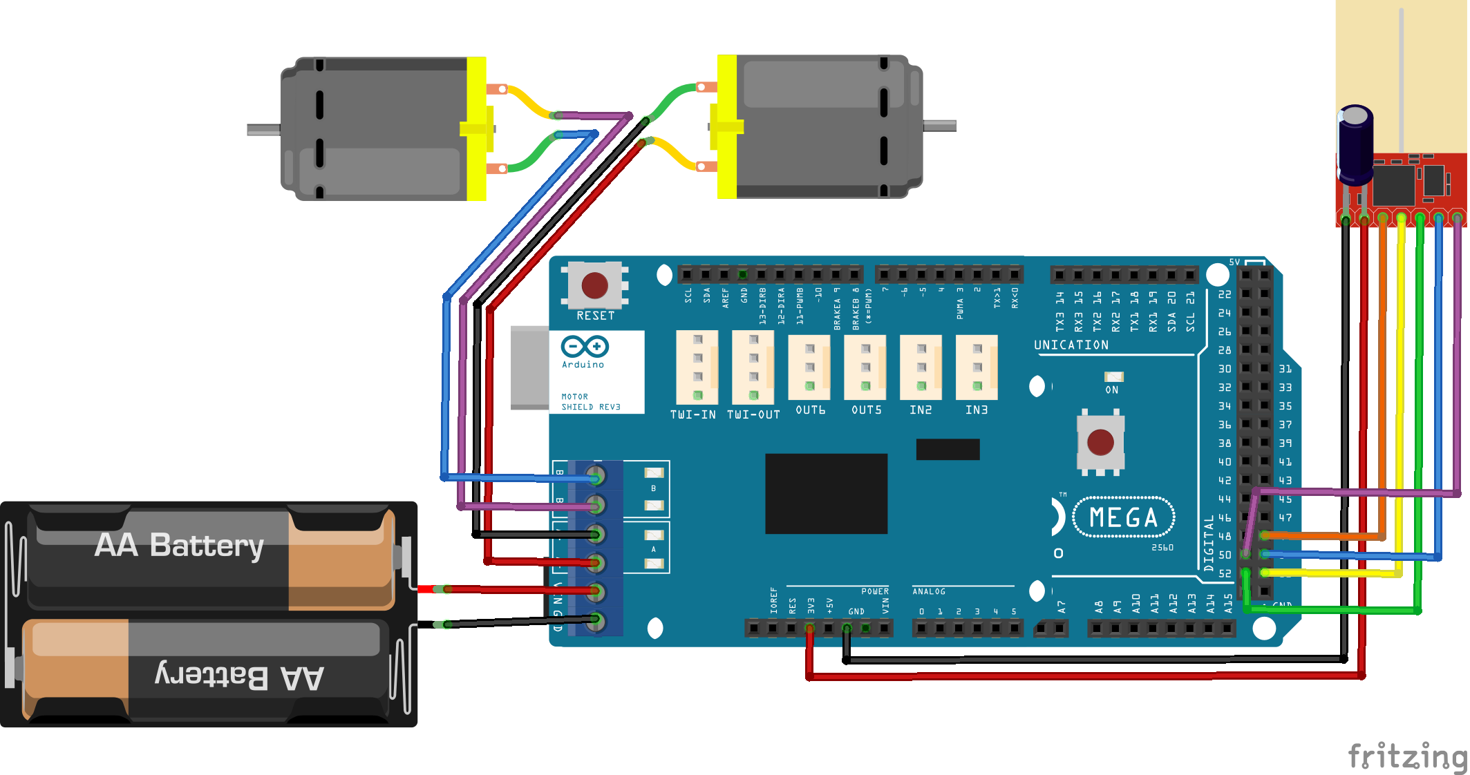
Car Side If you are using the low powered nrf24 and are going to directly connect power to the Arduino Mega, you will need to solder the power and ground from the nrf24 directly to the 3.3 volt pin on the bottom of the Mega since the motor controller likely wont break out the 3.3 volts. You should be able to just use the female breakouts for the rest. The power will be supplied from the motor controller.
| NRF24 | Uno | Mega |
| 1 | GND | GND |
| 2 | 3.3v | 3.3v |
| 3 | 9 | 49 |
| 4 | 10 | 53 |
| 5 | 13 | 52 |
| 6 | 11 | 51 |
| 7 | 12 | 50 |
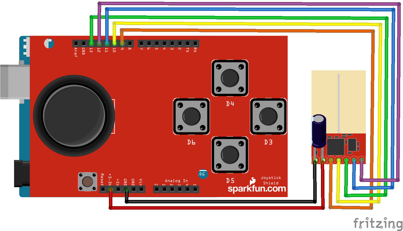
Controller Side Connect the joystick shield and solder each nrf24 connection to the pins on the top of the shield or bottom of the arduino. Unless your shield has breakouts on the top, then you can just plug them in.
The TX (Controller) Code from arduino-info
/* YourDuinoStarter Example: nRF24L01 Transmit Joystick values

- WHAT IT DOES: Reads Analog values on A0, A1 and transmits

them over a nRF24L01 Radio Link to another transceiver.

- SEE the comments after "//" on each line below

- CONNECTIONS: nRF24L01 Modules See:

http://arduino-info.wikispaces.com/Nrf24L01-2.4GHz-HowTo

1 - GND

2 - VCC 3.3V !!! NOT 5V

3 - CE to Arduino pin 9

4 - CSN to Arduino pin 10

5 - SCK to Arduino pin 13

6 - MOSI to Arduino pin 11

7 - MISO to Arduino pin 12

8 - UNUSED

-

Analog Joystick or two 10K potentiometers:

GND to Arduino GND

VCC to Arduino +5V

X Pot to Arduino A0

Y Pot to Arduino A1
– V1.00 11/26/13
Based on examples at http://www.bajdi.com/
Questions: terry@yourduino.com */
/*—–( Import needed libraries )—–*/
#include <SPI.h>
#include <nRF24L01.h>
#include <RF24.h>
/*—–( Declare Constants and Pin Numbers )—–*/
#define CE_PIN 9
#define CSN_PIN 10
#define JOYSTICK_X A0
#define JOYSTICK_Y A1
// NOTE: the “LL” at the end of the constant is “LongLong” type
const uint64_t pipe = 0xE8E8F0F0E1LL; // Define the transmit pipe
/*—–( Declare objects )—–*/
RF24 radio(CE_PIN, CSN_PIN); // Create a Radio
/*—–( Declare Variables )—–*/
int joystick[2]; // 2 element array holding Joystick readings
void setup() /****** SETUP: RUNS ONCE ******/
{
Serial.begin(9600);
radio.begin();
radio.openWritingPipe(pipe);
}//–(end setup )—
void loop() /****** LOOP: RUNS CONSTANTLY ******/
{
joystick[0] = analogRead(JOYSTICK_X);
joystick[1] = analogRead(JOYSTICK_Y);
radio.write( joystick, sizeof(joystick) );
}//–(end main loop )—
/*—–( Declare User-written Functions )—–*/
//NONE
//*********( THE END )***********
The RX (Car) Code from seeedstudio, gpop1, and Me.
//. Motor driver shield- 2012 Copyright (c) Seeed Technology Inc.

//

// Original Author: Jimbo.we

// Contribution: LG

//

// This library is free software; you can redistribute it and/or

// modify it under the terms of the GNU Lesser General Public

// License as published by the Free Software Foundation; either

// version 2.1 of the License, or (at your option) any later version.

//

// This library is distributed in the hope that it will be useful,

// but WITHOUT ANY WARRANTY; without even the implied warranty of

// MERCHANTABILITY or FITNESS FOR A PARTICULAR PURPOSE. See the GNU

// Lesser General Public License for more details.

//

// You should have received a copy of the GNU Lesser General Public

// License along with this library; if not, write to the Free Software

// Foundation, Inc., 51 Franklin St, Fifth Floor, Boston, MA 02110-1301 USA
#include <SPI.h>
#include <nRF24L01.h>
#include <RF24.h>
/*—–( Declare Constants and Pin Numbers )—–*/
#define CE_PIN 49
#define CSN_PIN 53
// NOTE: the “LL” at the end of the constant is “LongLong” type
const uint64_t pipe = 0xE8E8F0F0E1LL; // Define the transmit pipe
/*—–( Declare objects )—–*/
RF24 radio(CE_PIN, CSN_PIN); // Create a Radio
int pinI1 = 8; //define I1 interface
int pinI2 = 11; //define I2 interface
int speedpinA = 9; //enable motor A
int pinI3 = 12; //define I3 interface
int pinI4 = 13; //define I4 interface
int speedpinB = 10; //enable motor B
int fspead = 0; //define the forward spead of motor
int bspead = 0; //define the backward spead of motor
int rspead = 0; //define the right turn only spead of motor
int lspead = 0; //define the left turn only spead of motor
int joystick[2]; // 2 element array holding Joystick readings
byte flagStop = 0;
void setup()
{
pinMode(pinI1, OUTPUT);
pinMode(pinI2, OUTPUT);
pinMode(speedpinA, OUTPUT);
pinMode(pinI3, OUTPUT);
pinMode(pinI4, OUTPUT);
pinMode(speedpinB, OUTPUT);
Serial.begin(9600);
//delay(250);
Serial.println(“Nrf24L01 Receiver Starting”);
radio.begin();
radio.openReadingPipe(1, pipe);
radio.startListening();;
}
void forward()
{//if (joystick[1] >= 510)//ok
fspead = map(joystick[1], 510, 1023, 0, 255);
Serial.print(“Forward::::”);
Serial.print(“A: “);
Serial.print(fspead);
Serial.print(“B: “);
Serial.print(fspead);
Serial.println(“”);
digitalWrite(pinI4, HIGH); //turn DC Motor B move clockwise
digitalWrite(pinI3, LOW);
digitalWrite(pinI2, LOW); //turn DC Motor A move anticlockwise
digitalWrite(pinI1, HIGH);
analogWrite(speedpinA, fspead); //input a simulation value to set the speed
analogWrite(speedpinB, fspead);
}
void backward()//if (joystick[1] <= 505) { bspead = map(joystick[1], 506, 0, 0, 255); Serial.print(“Backward: “); Serial.print(“A: “); Serial.print(bspead); Serial.print(“B: “); Serial.print(bspead); Serial.println(“”); digitalWrite(pinI4, LOW); //turn DC Motor B move anticlockwise digitalWrite(pinI3, HIGH); digitalWrite(pinI2, HIGH); //turn DC Motor A move clockwise digitalWrite(pinI1, LOW); analogWrite(speedpinA, bspead); //input a simulation value to set the speed analogWrite(speedpinB, bspead); } void left()//if (joystick[0] >= 516)
{
lspead = map(joystick[0], 517, 1023, 0, 255);
Serial.print(“Left Only: “);
Serial.print(“A: “);
Serial.print(lspead);
Serial.print(“B: “);
Serial.print(lspead);
Serial.println(“”);
digitalWrite(pinI4, HIGH); //turn DC Motor B move clockwise
digitalWrite(pinI3, LOW);
digitalWrite(pinI2, HIGH); //turn DC Motor A move clockwise
digitalWrite(pinI1, LOW);
analogWrite(speedpinA, lspead); //input a simulation value to set the speed
analogWrite(speedpinB, lspead);
}
void right()//if (joystick[0] <= 508) { rspead = map(joystick[0], 517, 0, 0, 255); Serial.print(“Right Only: “); Serial.print(“A: “); Serial.print(rspead); Serial.print(“B: “); Serial.print(rspead); Serial.println(“”); digitalWrite(pinI4, LOW); //turn DC Motor B move anticlockwise digitalWrite(pinI3, HIGH); digitalWrite(pinI2, LOW); //turn DC Motor A move clockwise digitalWrite(pinI1, HIGH); analogWrite(speedpinA, rspead); //input a simulation value to set the speed analogWrite(speedpinB, rspead); } void forandright()//if (joystick[1] >= 516)
//not perfect but useable
{
fspead = map(joystick[1], 513, 1023, 0, 255);
Serial.print(“Forward and Right: “);
Serial.print(“A: “);
Serial.print(fspead);
Serial.print(“B: “);
Serial.print(fspead / 2);
Serial.println(“”);
digitalWrite(pinI4, HIGH); //turn DC Motor B move clockwise
digitalWrite(pinI3, LOW);
digitalWrite(pinI2, LOW); //turn DC Motor A move anticlockwise
digitalWrite(pinI1, HIGH);
analogWrite(speedpinA, fspead); //input a simulation value to set the speed
analogWrite(speedpinB, fspead / 2);
}
void forandleft()//if (joystick[1] >= 516)
{
fspead = map(joystick[1], 513, 1023, 0, 255);
Serial.print(“Forward and Left: “);
Serial.print(“A: “);
Serial.print(fspead / 2);
Serial.print(“B: “);
Serial.print(fspead);
Serial.println(“”);
digitalWrite(pinI4, HIGH); //turn DC Motor B move clockwise
digitalWrite(pinI3, LOW);
digitalWrite(pinI2, LOW); //turn DC Motor A move anticlockwise
digitalWrite(pinI1, HIGH);
analogWrite(speedpinA, fspead / 2); //input a simulation value to set the speed
analogWrite(speedpinB, fspead);
}
void backandright()//
{
bspead = map(joystick[1], 517, 0, 255, 0);
Serial.print(“Back and Right: “);
Serial.print(“A: “);
Serial.print(bspead);
Serial.print(“B: “);
Serial.println(“”);
Serial.print(bspead / 2);
digitalWrite(pinI4, LOW); //turn DC Motor B move anticlockwise
digitalWrite(pinI3, HIGH);
digitalWrite(pinI2, HIGH); //turn DC Motor A move clockwise
digitalWrite(pinI1, LOW);
analogWrite(speedpinA, bspead); //input a simulation value to set the speed
analogWrite(speedpinB, bspead / 2);
}
void backandleft()//
{
bspead = map(joystick[1], 517, 0, 0, 255);
Serial.print(“Back and Left: “);
Serial.print(“A: “);
Serial.print(bspead / 2);
Serial.print(“B: “);
Serial.print(bspead);
Serial.println(“”);
digitalWrite(pinI4, LOW); //turn DC Motor B move anticlockwise
digitalWrite(pinI3, HIGH);
digitalWrite(pinI2, HIGH); //turn DC Motor A move clockwise
digitalWrite(pinI1, LOW);
analogWrite(speedpinA, bspead / 2); //input a simulation value to set the speed
analogWrite(speedpinB, bspead);
}
void stop()//
{
Serial.println(“ALL STOP”);
digitalWrite(speedpinA, LOW); // Unenble the pin, to stop the motor. this should be done to avid damaging the motor.
digitalWrite(speedpinB, LOW);
//delay(500);
}
void loop()
{
if ( radio.available() )
{
// Read the data payload until we’ve received everything
bool done = false;
radio.read(joystick, sizeof(joystick));
// Serial.print(“X = “);
// Serial.print(joystick[0]);
// Serial.print(” Y = “);
// Serial.println(joystick[1]);
flagStop = 0;
} else {
stop();
flagStop = 1;
Serial.println(“No radio available”);
}
if (joystick[1] > 502 && joystick[1] < 510 && joystick[0] >= 509 && joystick[0] <= 510)
{
stop();
flagStop = 1;
}
else {
flagStop = 0;
}
if (flagStop == 0) {//if the flag is 1 then skip this code until its not
if (joystick[0] <= 508 && joystick[1] >= 516)// J0 center stick 509 to 510. j1 center stick 503 to 509.
{
forandright();
}
else if (joystick[0] >= 513 && joystick[1] >= 516)// J0 center stick 509 to 510. j1 center stick 503 to 509.
{
forandleft();
}
else if (joystick[0] <= 508 && joystick[1] <= 502)// J0 center stick 509 to 510. j1 center stick 503 to 509. { backandright(); } else if (joystick[0] >= 513 && joystick[1] <= 502)// J0 center stick 509 to 510. j1 center stick 503 to 509.
{
backandleft();
}
else if (joystick[1] <= 505 && joystick[0] >= 509 && joystick[0] <= 513)// J0 center stick 509 to 510. j1 center stick 503 to 509. { backward(); } else if (joystick[1] >= 510 && joystick[0] <= 513 && joystick[0] >= 509)// J0 center stick 509 to 510. j1 center stick 503 to 509.
{
forward();
}
else if (joystick[0] >= 516)// J0 center stick 509 to 510. j1 center stick 503 to 509.
{
left();
}
else if (joystick[0] <= 508)// J0 center stick 509 to 510. j1 center stick 503 to 509.
{
right();
}
else
{ // no harm as a back up
stop();
}
}
}

You must log in to post a comment.