Using a 433 MHz transmitter and receiver , a Dallas DS18B20, and a 16×2 LCD with an i2c / SPI character LCD backpack we can make a simple wireless temperature monitor. I’m not going to go into the construction of the hardware here since there is plenty of resources out there for that already.
!Antennas!
Antennas are a big deal! There is a ton of antenna theory and math out there for you to figure it out but it would be difficult for anyone not already involved in antennas. So, I’m going to tell you what I did.
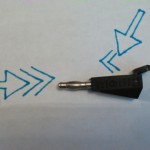
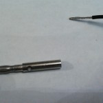
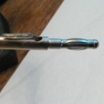
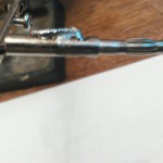
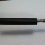
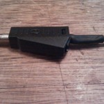
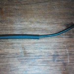
I got 2 stainless steel whips and magnetic bases from a local 2-way radio supplier and cut the whips to 13 1/4 inches. No coil is needed for this. I get about 60 feet through walls and floors. On the transmitter I am using 12 volts so that I can transmit at full power. I am just using one of the 5 volt pins of the Uno to power the receiver.
Transmitter Code
#include <OneWire.h> //This temperature sensor requires a 4.7k Ohm resistor across its pins 2 and three!!!!
#include <DallasTemperature.h>
#include <Wire.h>
#include <VirtualWire.h>
int ledPin = 13;//Set up the TX indicator pin 13 as LedPin
int Sensor1Data;//initialize the use of the variable Sensor1Data
//int sensorValue = 0;  // variable to store the value coming from the sensor If using analog sensor
float currentTemp = 0;//to store decimal value coming from the temp sensor
// RF Transmission container
//char Sensor1CharMsg[4];
// Trying to use 5 instead to fit trailing null char
// go back to 4 if this does not work.
char Sensor1CharMsg[5];

//This temperature sensor requires a 4.7k Ohm resistor across its pins 2 and three!!!! Thats the middle pin and the GND pin
// Data wire is plugged into pin 2 on the Arduino
#define ONE_WIRE_BUS 2

// Setup a oneWire instance to communicate with any OneWire devices
OneWire oneWire(ONE_WIRE_BUS);

// Pass our oneWire reference to Dallas Temperature.
DallasTemperature sensors(&oneWire);

DeviceAddress insideThermometer = { 0x28, 0xE4, 0x10, 0x74, 0x03, 0x00, 0x00, 0xD5 };
// DeviceAddress outsideThermometer = { 0x28, 0x20, 0x04, 0xA8, 0x02, 0x00, 0x00, 0x4D };

void setup()
{
  pinMode(ledPin, OUTPUT);//Set the ledPin as an output
  Serial.begin(9600);//initialize serial communication
  Serial.print("TX Start");//Print TX Start in the serial terminal
  // VirtualWire
    // Initialise the IO and ISR
    // Required for DR3100
    //vw_set_ptt_inverted(true);
    // Bits per sec
    vw_setup(300);	//Set VirtualWire communication speed
// Start up the library
sensors.begin();
// set the resolution to 9 bit (good enough?)
sensors.setResolution(insideThermometer, 9);
// sensors.setResolution(outsideThermometer, 9);
}

void loop(void)
{

sensors.requestTemperatures();  //Get temperature from the temp Sensor

float tempC = sensors.getTempC(insideThermometer);
if (tempC == -127.00) {
Serial.print("Error");//Print Error if we read -127
} else {
// lcd.print(tempC);
// lcd.print("/");
Sensor1Data = (DallasTemperature::toFahrenheit(tempC));//Set Sensor1Data as the Celcius to Fahrenheit Conversion
Serial.print(Sensor1Data); //Print the converted temp in the serial terminal
// Integer to ASCII
itoa(Sensor1Data,Sensor1CharMsg,10);
digitalWrite(13, true); // Turn on a light to show transmitting
 vw_send((uint8_t *)Sensor1CharMsg, strlen(Sensor1CharMsg));//Send the data collected

 vw_wait_tx(); // Wait until the whole message is gone
 digitalWrite(13, false); // Turn off a light after transmission
 delay(200);//Wait 200 Milliseconds and then go back to program start
}

}
Receiver Code
#include <Wire.h>

#include <Adafruit_MCP23008.h>
#include <LiquidCrystal.h>

/*

Sensor Receiver
By Markus Ulfberg 2012-07-06

Gets a sensor reading 0-1023 in a char array
from RF Transmitter unit via VirtualWire
converts char array back to integer

*/

#include <VirtualWire.h>

// LED's
int ledPin = 13;//Set up pin 13 as the recieve indicator
int ActionLED = 4;//Set up pin for LED

// Connect via i2c, default address #0 (A0-A2 not jumpered)
LiquidCrystal lcd(0);
// Sensors
int Sensor1Data;//initialize the variable Sensor1Data for use

// RF Transmission container
 char Sensor1CharMsg[4];
// Trying to use 5 instead to fit trailing null char
// go back to 4 if this does not work.
//char Sensor1CharMsg[5];

void setup() {
  lcd.begin(16, 2);
  Serial.begin(9600);//Initialize serial communication
  Serial.print("RX Start");//Print RX Start in the Serial Terminal

  // sets the digital pin as output
  pinMode(ledPin, OUTPUT);//Set the ledPin as an Output
  pinMode(ActionLED, OUTPUT);//Se up the ActionLED pin as an Output
  digitalWrite(ActionLED, LOW);//Set the ActionLED LOW 'off'

    // VirtualWire
    // Initialise the IO and ISR
    // Required for DR3100
    //vw_set_ptt_inverted(true);
    // Bits per sec
    vw_setup(300);//Set up VirualWire Communication Speed

    // Start the receiver PLL running
    vw_rx_start();

} // END void setup

void loop(){
  //Unsigned Integer of 8 bit length buffer Max Message Length
    uint8_t buf[VW_MAX_MESSAGE_LEN];
  //Unsigned Integer of 8 bit length buffer length Max Message Length
    uint8_t buflen = VW_MAX_MESSAGE_LEN;

    // Non-blocking
    if (vw_get_message(buf, &buflen))
    {
	int i;//initialize the variable i
        // Turn on a light to show received good message
        digitalWrite(13, true);
        lcd.setCursor(1, 0);
	lcd.print("Remote Temp: ");//Print Remote Temp: in the serial terminal
        // Message with a good checksum received, dump it.
        for (i = 0; i < buflen; i++)//Use the variable i to store bytes from message and if i is less than the buffer length then increase byte storage.
	{
          // Fill Sensor1CharMsg Char array with corresponding
          // chars from buffer.
         Sensor1CharMsg[i] = char(buf[i]);//Senso1CharMsg[i] is the variable to represent char(buf[i]);, char(buf[i]); is charactor buffer storage
	}

        // Null terminate the char array
        // This needs to be done otherwise problems will occur
        // when the incoming messages has less digits than the
        // one before.
        Sensor1CharMsg[buflen] = '\0';//clear it to fill again.

        // Sensor1Data is atoi (ASCII to Integer) from Sensor1CharMsg
        Sensor1Data = atoi(Sensor1CharMsg);

        // DEBUG

        lcd.println(Sensor1Data); //Print Sensor1Data in the serial Terminal

        // END DEBUG

        // Turn off light to and await next message
        digitalWrite(13, false);
        //If Sensor1Data (temp) is less than 75 degrees turn on the ActionLED
        if (Sensor1Data < 75)
        {
          digitalWrite(ActionLED, HIGH);
        }
        delay(100);
    } //If Sensor1Data (temp)is more than 75 degrees turn off ActionLE
        else if (Sensor1Data > 75)
        {
          digitalWrite(ActionLED, LOW);
        }

    }
