UPDATE 8/8/15
This post still gets quite a few views every day. If you build something using this post I would love to see what you’ve made. Please send pictures of your completed projects to [email protected] along with any suggestions or comments you may have. I will be making a post to show them off.
UPDATE 4/21/13
Added fan only option to thermostat in code and added a switch to control it..
Cleaned up code
Added diagnostic Serial.print statements
Added threshold of +/- 3 degrees of set temperature.
UPDATE 1/30/13
Fixed download links for sketches
UPDATE 1/13/13
Updated tutorial using an I2C to interface the LCD to the Arduino, saving some of those much needed digital ports for other useful expansions and improvements. Read on and I hope you find it helpful. Leave me some comments or reach me on facebook, or google +.
::::::::::::::::::::::::::::::::::::::::::::::::::::::::::::::::::::::::::::::::::::::::::::::::::::::::::::::::
UPDATE:::::::::::::::::::::::::::::::::::::::::::::::::::::::::::::::::::::::::::::::::::::::::::::::::::
If you have questions…. Please Ask!
Added Code for finding the address of a DS18B20 Temerature sensor.
UPDATE 12/8/2012
:::::::::::::::::::::::::::::::::::::::::::::::::::::::::::::::::::::::::::::::::::::::::::::::::::::::::
I have decided to use a IIC/I2C/TWI/SPI Serial Interface to reduce the number of digital ports used on my Arduino for future expansion. Read further for the Updated code and improvements.
:::::::::::::::::::::::::::::::::::::::::::::::::::::::::::::::::::::::::::::::::::::::::::::::::::::::::::::::
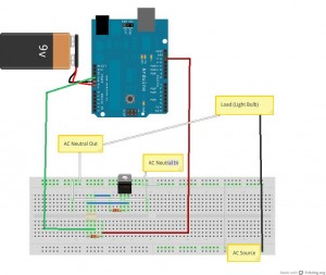
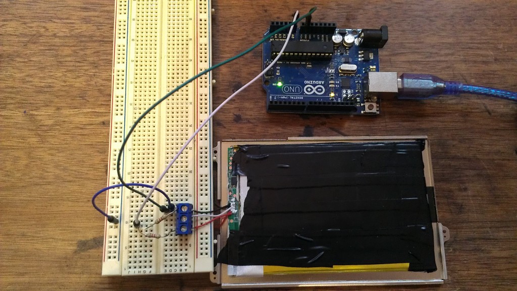
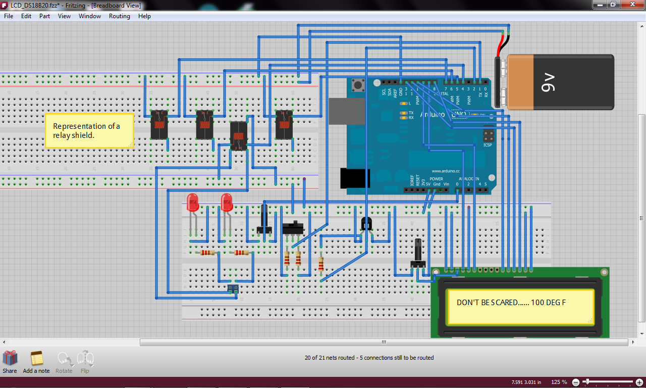
This tutorial assumes you know how to properly hook up switches to the arduino and otherwise have some basic knowlege of how electricity works.
I will be adding a full physical connections tutorial for this thermostat in the near future.
I built this using the Arduino Uno Rev 3, relay shield from seeedstudio, Dallas DS18B20, and an 16×2 LCD.
Hardware Required:
Arduino Uno Rev 3
Relay Shield
Dallas DS18B20 One Wire Temperature Sensor (Datasheet)
16×2 LCD (Datasheet)
I2C interface ( you could just buy an LCD that already has an I2C interface on it)
1 10 K Ohm Potentiometer
2 Single Pole double Throw Rocker Switches
1 Red LED indicator for heating mode
1 Blue LED indicator for cooling mode
2 10 K Ohm Resistors
1 4.7 K Ohm Resistor
1 10 K Ohm Trimmer Potentiometer (if not using the I2C)
Wire
You need to install the libraries for the Dallas DS18B20 and also for using the LCD with an I2C. You can get them both here. You will also need to rename or move the original LiquidCrystal library if you are going to use an I2C with your LCD. If you don’t know how to work with libraries please visit arduino.cc.
This is all I have for now but I will be updating very soon!
Use this code to find the address of your DS18B20 Sensor.Download the Sketch Here
DS18B20 Address Finder::::
// This sketch looks for 1-wire devices and
// prints their addresses (serial number) to
// the UART, in a format that is useful in Arduino sketches
// Tutorial:
// http://www.hacktronics.com/Tutorials/arduino-1-wire-address-finder.html
#include <OneWire.h>
OneWire ds(3); // Connect your 1-wire device to pin 3
void setup(void) {
Serial.begin(9600);
discoverOneWireDevices();
}
void discoverOneWireDevices(void) {
byte i;
byte present = 0;
byte data[12];
byte addr[8];
Serial.print(“Looking for 1-Wire devices…\n\r”);
while(ds.search(addr)) {
Serial.print(“\n\rFound \’1-Wire\’ device with address:\n\r”);
for( i = 0; i < 8; i++) {
Serial.print(“0x”);
if (addr[i] < 16) {
Serial.print(‘0′);
}
Serial.print(addr[i], HEX);
if (i < 7) {
Serial.print(“, “);
}
}
if ( OneWire::crc8( addr, 7) != addr[7]) {
Serial.print(“CRC is not valid!\n”);
return;
}
}
Serial.print(“\n\r\n\rThat’s it.\r\n”);
ds.reset_search();
return;
}
void loop(void) {
// nothing to see here
}
Thermostat Code without the I2C interface:::: Download the Sketch Here
/* A fair portion of the code here is from Arduinotronics and I would have been lost with out it. This is my first “big” Arduino project. So, there is probably a ton of things that can be improved on and tweeked. I would love to know your thoughts and see your improvements! If you would like to share your thoughts with me on this please email me at modsbyus at modsbyus dot com and make the subject line RE: Arduino Thermostat Thoughts, or write a comment on the tutorial at http://www.modsbyus.com/diy-arduino-thermostat. Required library for the DS18B20 can be downloaded here.. http://cloud.modsbyus.com/public.php?service=files&t=82892f20b1296b9557303d6dc60b2f5a/ */
#include <OneWire.h> /*This temperature sensor requires a 4.7k Ohm resistor across its pins 2 and three!!!! */
#include <DallasTemperature.h>
#include <LiquidCrystal.h>
int sensorPin = A0; // select the input pin for the 10K potentiometer
int sensorValue = 0; // variable to store the value coming from the sensor
int setTemp = 0; // variable to store temp desired
int SSRCPin = 5; //Turn on A/C unit
int SSRHPin = 6; //Turn on heat (electric or gas)
int hcLED = 4; //indicator for Cooling mode
int SwitchPin = 1; // To switch between Cooling and Heating
int SSRFan = 7; // To turn on and off the air handler fan
float currentTemp = 0; //Store the current tempurature
// LCD Wires from LCD/to Arduino and other components
// 1 to GND
// 2 to 5V
// 3 to Trimmer Pot Reference Pin
// 4 to Arduino Pin 9
// 5 to GND
// 6 to Arduino Pin 10
// 11 to Arduino Pin 11
// 12 to Arduino Pin 12
// 13 to Arduino Pin 13
// 14 to Arduino Pin 8
// 15 to 5V
// 16 to GND
//Heat relay to Arduino pin 4
//Cooling relay to Arduino pin 5
//Fan relay to Arduino pin 6
//LEDs relay to Arduino pin 7
//DS18B20 to Arduino pin 2
//Heat/Cool switch to Arduino pin 1
LiquidCrystal lcd(9, 10, 11, 12, 13, 8);
/*This temperature sensor requires a 4.7k Ohm resistor across its pins 2 and three!!!! Thats the middle pin and the VDD pin */
// Data wire is plugged into pin 2 on the Arduino
#define ONE_WIRE_BUS 2
// Setup a oneWire instance to communicate with any OneWire devices
OneWire oneWire(ONE_WIRE_BUS);
// Pass our oneWire reference to Dallas Temperature.
DallasTemperature sensors(&oneWire);
DeviceAddress insideThermometer = { 0x28, 0xF0, 0xEA, 0x73, 0x03, 0x00, 0x00, 0xCF };
// DeviceAddress outsideThermometer = { 0x28, 0x20, 0x04, 0xA8, 0x02, 0x00, 0x00, 0x4D };
void setup(void)
{
// Start up the library
sensors.begin();
// set the resolution to 9 bit (good enough?)
sensors.setResolution(insideThermometer, 9);
// sensors.setResolution(outsideThermometer, 9);
lcd.begin(16,2); // columns, rows. use 16,2 for a 16×2 LCD, etc.
pinMode(SSRFan, OUTPUT); //set air handler fan pin as output
digitalWrite(SSRFan, LOW);//Set the fan relay pin normally low (off)
pinMode(SSRHPin, OUTPUT);//Set the heat relay pin as an output
digitalWrite(SSRHPin, LOW);//Set the heat relay pin as normally low (off)
pinMode(SSRCPin, OUTPUT);//Set the cooling relay pin as an output
digitalWrite(SSRCPin, LOW);//Set the cooling relay pin as normally low (off)
pinMode(hcLED, OUTPUT);//Set the indicator LED pin as an output
digitalWrite(hcLED, LOW);//Set the LED indicator pin as normally low (cooling indication)
pinMode(SwitchPin, INPUT);//Set the switch pin as an input
}
void printTemperature(DeviceAddress deviceAddress)
{
sensors.requestTemperatures(); //Get temperature from DS18B20
float tempC = sensors.getTempC(deviceAddress);
if (tempC == -127.00) {
lcd.print(“Error”);
} else {
// lcd.print(tempC);
// lcd.print(“/”);
currentTemp = (DallasTemperature::toFahrenheit(tempC));
lcd.print(currentTemp);
}
}
void loop(void)
{
delay(500);
sensorValue = analogRead(sensorPin); //Set the variable ‘sensorValue’ as and analog read of the sensor pin
setTemp = sensorValue / 10.24; //Gives us a set temp range between 0 and 99 degrees
lcd.clear(); // start with a blank screen
lcd.setCursor(0,0); //Set the cursor to the 1st position on the 1st line
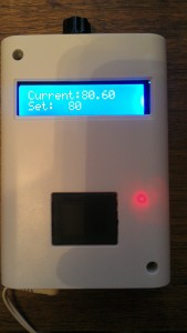
lcd.print(“Current:”); //Print the word ‘Current:’
lcd.setCursor(0,1);//Set the cursor to the 1st position on the second line
lcd.print(“Set:”); //Print the word ‘Set:’
//lcd.setCursor(0,3);
//lcd.print(“Heat: “);
lcd.setCursor(8,0);// Set the cursor to position 8 on the 1st line
printTemperature(insideThermometer);//Print the temperature read from the DS18B20
lcd.setCursor(6,1);//Set the cursor to the position 6 on the 2nd line
lcd.print(setTemp); //Print the value read from the potentiometer
//lcd.setCursor(7,3);
//lcd.print(heat);
//Cooling Mode
int val = digitalRead(SwitchPin) ;// val represents digitalRead(SwitchPin);
/* If the value of is equal to 1 (high) then make hcLED low (off) which sets the relay in a normally closed state. Hence, turning on the blue LED. */
if (val == 1)
{
digitalWrite(hcLED, LOW);//Set the heating/cooling LED indicator to LOW if ‘val’ is equal to 1
}
/* If the SwitchPin reads 1 and the current temperature is greater than the set temperature (if its hot) turn on the A/C and internal fan */
if (val == 1 && (currentTemp > setTemp))
{
digitalWrite(SSRFan, HIGH);//Set the fan relay high
digitalWrite(SSRHPin, LOW);//Set the heat relay low
digitalWrite(SSRCPin, HIGH);//Set the cooling relay high
}
/* Otherwise, if the SwitchPin reads 1 and the current temperature is less than the set temperature (the set temperature has been reached), turn off the A/C and internal fan */
else if (val == 1 && (currentTemp < setTemp))
{
digitalWrite(SSRCPin, LOW);//Set the cooling relay low
digitalWrite(SSRFan, LOW);//Set the fan relay low
}
// Heating Mode
/* If the value of is 0 then make hcLED HIGH (on) which sets the relay in a normally open state. Hence, turning on the RED LED */
if (val == 0)
{
digitalWrite(hcLED, HIGH);//Set the heating/cooling led high
}
/* If the SwitchPin reads 0 and the current temperature is less than the set temperature (if its cold) turn on the HEAT and internal fan */
if (val == 0 && (currentTemp < setTemp))
{
digitalWrite(SSRFan, HIGH);//Set the fan relay high
digitalWrite(SSRCPin, LOW);//Set the cooling relay low
digitalWrite(SSRHPin, HIGH);//Set the heat relay high
}
/* If the SwitchPin reads 0 and the current temperature is greater than the set temperature (the set temperature has been reached) turn off the HEAT and internal fan */
else if (val == 0 && (currentTemp > setTemp))
{
digitalWrite(SSRHPin, LOW);//Set the heat relay low
digitalWrite(SSRFan, LOW);//Set the fan relay low
}
}
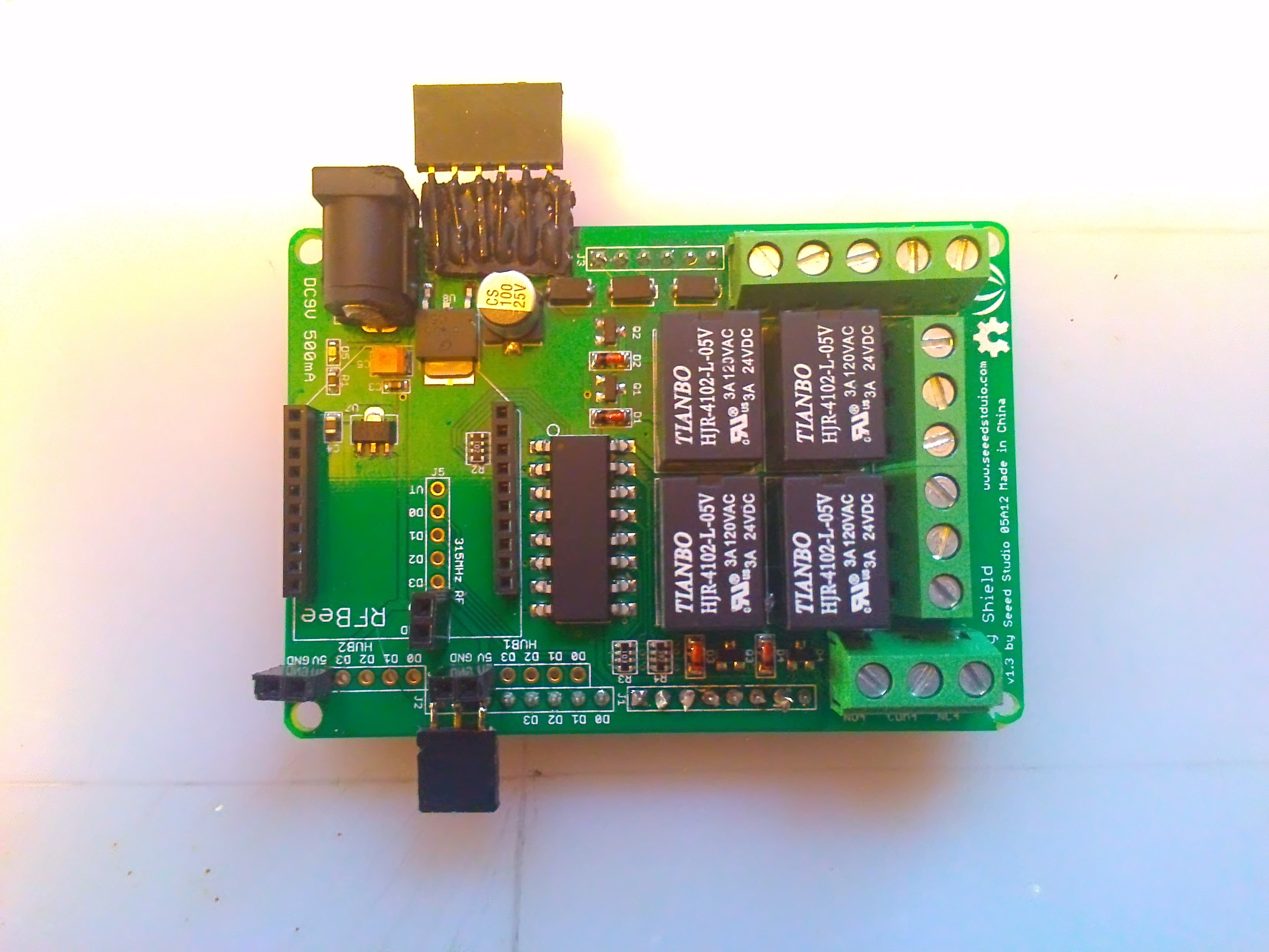
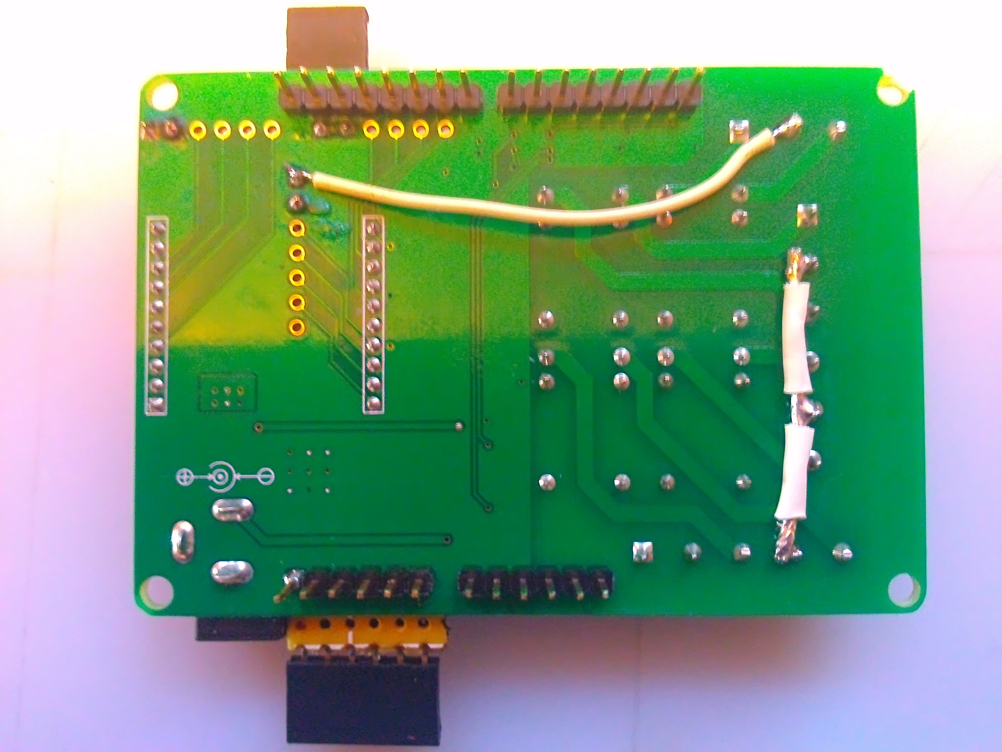
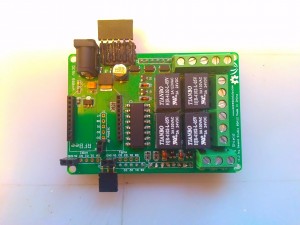
You will need to add some things to the Relay Shield. A couple of pictures should do. Add some female headers and a couple of jumpers. The jumper wire on the right in the bottom picture is to bridge all the common terminals together for the 24 volts coming from the HVAC unit. The longer wire is taking ground to the common terminal for the LEDs used for indicating heat and cool mode.

Thermostat Code with I2C Interface::: Download the Sketch Here
/* A fair portion of the code here is from Arduinotronics and I would have been lost with out it. This is my first “big” Arduino project. So, there is probably a ton of things that can be improved on and tweeked. I would love to know your thoughts and see your improvements! If you would like to share your thoughts with me on this please email me at modsbyus at modsbyus dot com and make the subject line RE: Arduino Thermostat Thoughts, or write a comment on the tutorial at http://www.modsbyus.com/diy-arduino-thermostat Required libraries for the DS18B20 and the I2C LCD can be downloaded here.. http://cloud.modsbyus.com/public.php?service=files&file=/admin/files/Modsbyus/libraries.rar/ */
#include <OneWire.h> /*This temperature sensor requires a 4.7k Ohm resistor across its pins 2 and three!!!! */
#include <DallasTemperature.h>
#include <Wire.h>
#include <LCD.h>
#include <liquidcrystal_i2c.h> // F Malpartida’s NewLiquidCrystal library
#define I2C_ADDR 0x20 // Define I2C Address where the PCF8574A is
//Define all the I2C to LCD pin relationships
#define BACKLIGHT_PIN 7
#define En_pin 4
#define Rw_pin 5
#define Rs_pin 6
#define D4_pin 0
#define D5_pin 1
#define D6_pin 2
#define D7_pin 3
#define LED_OFF 0
#define LED_ON 1
LiquidCrystal_I2C lcd(I2C_ADDR,En_pin,Rw_pin,Rs_pin,D4_pin,D5_pin,D6_pin,D7_pin);
int sensorPin = A0; // select the input pin for the 10K potentiometer
int sensorValue = 0; // variable to store the value coming from the sensor
int setTemp = 0; // variable to store temp desired
int SSRCPin = 5; //Turn on A/C unit
int SSRHPin = 6; //Turn on heat (electric or gas)
int hcLED = 4; //indicator for Cooling mode
int SwitchPin = 1; // To switch between Cooling and Heating
int SSRFan = 7; // To turn on and off the air handler fan
float currentTemp = 0;//Store current temperature
//Heat relay to Arduino pin 4
//Cooling relay to Arduino pin 5
//Fan relay to Arduino pin 6
//LEDs relay to Arduino pin 7
//DS18B20 to Arduino pin 2
//Heat/Cool switch to Arduino pin 1
/*This temperature sensor requires a 4.7k Ohm resistor across its pins 2 and three!!!! Thats the middle pin and the VDD pin */
// Data wire is plugged into pin 2 on the Arduino
#define ONE_WIRE_BUS 2
// Setup a oneWire instance to communicate with any OneWire devices
OneWire oneWire(ONE_WIRE_BUS);
// Pass our oneWire reference to Dallas Temperature.
DallasTemperature sensors(&oneWire);
DeviceAddress insideThermometer = { 0x28, 0xE4, 0x89, 0x6B, 0x04, 0x00, 0x00, 0x49 };
// DeviceAddress outsideThermometer = { 0x28, 0x20, 0x04, 0xA8, 0x02, 0x00, 0x00, 0x4D };
void setup(void)
{
// Start up the library
sensors.begin();//Start the DS18B20 sensor
// set the resolution to 9 bit (good enough?)
sensors.setResolution(insideThermometer, 9);
// sensors.setResolution(outsideThermometer, 9);
lcd.begin(16,2); // columns, rows. use 16,2 for a 16×2 LCD, etc.
pinMode(SSRFan, OUTPUT); //set air handler fan pin as output
digitalWrite(SSRFan, LOW);//Set the fan relay pin normally low (off)
pinMode(SSRHPin, OUTPUT);//Set the heat relay pin as an output
digitalWrite(SSRHPin, LOW);//Set the heat relay pin as normally low (off)
pinMode(SSRCPin, OUTPUT);//Set the cooling relay pin as an output
digitalWrite(SSRCPin, LOW);//Set the cooling relay pin as normally low (off)
pinMode(hcLED, OUTPUT);//Set the indicator LED pin as an output
digitalWrite(hcLED, LOW);//Set the LED indicator pin as normally low (cooling indication)
pinMode(SwitchPin, INPUT);//Set the switch pin as an input
}
void printTemperature(DeviceAddress deviceAddress)
{
sensors.requestTemperatures(); // Get the current tempurature
float tempC = sensors.getTempC(deviceAddress);
if (tempC == -127.00) {
lcd.print(“Error”);
} else {
// lcd.print(tempC);
// lcd.print(“/”);
currentTemp = (DallasTemperature::toFahrenheit(tempC));//Convert Celsius to Fahrenheit
lcd.print(currentTemp); //Print the current tempurature
}
}
void loop(void)
{
delay(500);//Delay for 1/2 second
sensorValue = analogRead(sensorPin);//Set the variable ‘sensorValue’ as an analog read of the sensor pin
setTemp = sensorValue / 10.24; //Gives us a set temp range between 0 and 99 degrees
//lcd.clear(); // start with a blank screen
lcd.setCursor(0,0); //Set the cursor to the 1st position on the 1st line
lcd.print(“Current:”); //Print the word ‘Current:’
lcd.setCursor(0,1);//Set the cursor to the 1st position on the second line
lcd.print(“Set:”); //Print the word ‘Set:’
//lcd.setCursor(0,3);
//lcd.print(“Heat: “);
lcd.setCursor(8,0);// Set the cursor to position 8 on the 1st line
printTemperature(insideThermometer);//Print the temperature read from the DS18B20
lcd.setCursor(6,1);//Set the cursor to the position 6 on the 2nd line
lcd.print(setTemp); //Print the value read from the potentiometer
//lcd.setCursor(7,3);
//lcd.print(heat);
//Cooling Mode
int val = digitalRead(SwitchPin) ;// val represents digitalRead(SwitchPin);
/* If the value of is 1 then make hcLED low (off) which sets the relay in a normally closed state. Hence, turning on the blue LED. */
if (val == 1)
{
digitalWrite(hcLED, LOW);//Set the heating/cooling indicator LED low
}
/* If the SwitchPin reads 1 and the current temperature is greater than the set temperature (if its hot) turn on the A/C and internal fan */
if (val == 1 && (currentTemp > setTemp))
{
digitalWrite(SSRFan, HIGH);//Set the fan relay pin high
digitalWrite(SSRHPin, LOW);//Set the heat relay pin low
digitalWrite(SSRCPin, HIGH);//Set the cooling relay pin high
}
/* Otherwise, if the SwitchPin reads 1 and the current temperature is less than the set temperature (the set temperature has been reached), turn off the A/C and internal fan */
else if (val == 1 && (currentTemp < setTemp))
{
digitalWrite(SSRCPin, LOW);//Set the cooling relay pin low
digitalWrite(SSRFan, LOW);//Set the fan relay low
}
// Heating Mode
/* If the value of is 0 then make hcLED HIGH (on) which sets the relay in a normally open state. Hence, turning on the RED LED */
if (val == 0)
{
digitalWrite(hcLED, HIGH);//Set the heating/cooling indicator LED high
}
/* If the SwitchPin reads 0 and the current temperature is less than the set temperature (if its cold) turn on the HEAT and internal fan */
if (val == 0 && (currentTemp < setTemp)) { digitalWrite(SSRFan, HIGH); digitalWrite(SSRCPin, LOW); digitalWrite(SSRHPin, HIGH); } /* If the SwitchPin reads 0 and the current temperature is greater than the set temperature (the set temperature has been reached) turn off the HEAT and internal fan */
else if (val == 0 && (currentTemp > setTemp))
{
digitalWrite(SSRHPin, LOW);//Set the heat relay pin low
digitalWrite(SSRFan, LOW);//Set the fan relay pin low
}
}
/blockquote>
Code with added Fan Function Download Here
/* A fair portion of the code here is from Arduinotronics and I would have been lost with out it. This is my first “big” Arduino project. So, there is probably a ton of things that can be improved on and tweeked. I would love to know your thoughts and see your improvements! If you would like to share your thoughts with me on this please email me at modsbyus at modsbyus dot com and make the subject line RE: Arduino Thermostat Thoughts, or write a comment on the tutorial at http://www.modsbyus.com/diy-arduino-thermostat/ */
#include <OneWire.h> //This temperature sensor requires a 4.7k Ohm resistor across its pins //2 and three!!!!
#include <DallasTemperature.h>
#include <Wire.h>
#include <LCD.h>
#include <LiquidCrystal_I2C.h> // F Malpartida’s NewLiquidCrystal library
#define I2C_ADDR 0x20 // Define I2C Address where the PCF8574A is
#define BACKLIGHT_PIN 7
#define En_pin 4
#define Rw_pin 5
#define Rs_pin 6
#define D4_pin 0
#define D5_pin 1
#define D6_pin 2
#define D7_pin 3
#define LED_OFF 0
#define LED_ON 1
LiquidCrystal_I2C lcd(I2C_ADDR,En_pin,Rw_pin,Rs_pin,D4_pin,D5_pin,D6_pin,D7_pin);
int sensorPin = A0; // select the input pin for the 10K potentiometer
int sensorValue = 0; // variable to store the value coming from the sensor
int setTemp = 0; // variable to store temp desired
int SSRCPin = 6; //Turn on A/C unit
int SSRHPin = 5; //Turn on heat (electric or gas)
int hcLED = 4; //indicator for Cooling mode
int SwitchPin = 3; // To switch between Cooling and Heating
int SSRFan = 7; // To turn on and off the air handler fan
float currentTemp = 0;
int FanPin = 8; //Fan Pin Switch
int FanVal = digitalRead(FanPin);
int val = digitalRead(SwitchPin) ;
//This temperature sensor requires a 4.7k Ohm resistor across its pins 2 and three!!!! Thats the middle pin and the GND pin
// Data wire is plugged into pin 2 on the Arduino
#define ONE_WIRE_BUS 2
// Setup a oneWire instance to communicate with any OneWire devices
OneWire oneWire(ONE_WIRE_BUS);
// Pass our oneWire reference to Dallas Temperature.
DallasTemperature sensors(&oneWire);
DeviceAddress insideThermometer = { 0x28, 0xAF, 0x51, 0x6C, 0x04, 0x00, 0x00, 0x22 };
// DeviceAddress outsideThermometer = { 0x28, 0x20, 0x04, 0xA8, 0x02, 0x00, 0x00, 0x4D };
void setup(void)
{
Serial.begin(9600);
// Start up the library
sensors.begin();
// set the resolution to 9 bit (good enough?)
sensors.setResolution(insideThermometer, 9);
// sensors.setResolution(outsideThermometer, 9);
lcd.begin (16,2); // columns, rows. use 16,2 for a 16×2 LCD, etc.
pinMode(SSRFan, OUTPUT); //set airhandler fan pin as output
pinMode(SSRHPin, OUTPUT);
pinMode(SSRCPin, OUTPUT);
pinMode(hcLED, OUTPUT);
pinMode(SwitchPin, INPUT);
pinMode(FanPin, INPUT);
}
void printTemperature(DeviceAddress deviceAddress)
{
sensors.requestTemperatures(); // was in loop
float tempC = sensors.getTempC(deviceAddress);
if (tempC == -127.00) {
lcd.print(“Error”);
} else {
// lcd.print(tempC);
// lcd.print(“/”);
currentTemp = (DallasTemperature::toFahrenheit(tempC));
lcd.print(currentTemp);
Serial.print(“Current Temp “);
Serial.println(currentTemp);
Serial.print(“Set Temp “);
Serial.println(setTemp);
}
}
void loop(void)
{
Serial.println(“Begin main Loop”);
int FanVal = digitalRead(FanPin);
int val = digitalRead(SwitchPin) ;
delay(500);
sensorValue = analogRead(sensorPin);
setTemp = sensorValue / 10.24; //Gives us a set temp range between 0 and 99 degrees
//lcd.clear(); // start with a blank screen
lcd.setCursor(0,0);
lcd.print(“Current:”);
lcd.setCursor(0,1);
lcd.print(“Set:”);
//lcd.setCursor(0,3);
//lcd.print(“Heat: “);
lcd.setCursor(8,0);
printTemperature(insideThermometer);
lcd.setCursor(6,1);
lcd.print(setTemp);
//lcd.setCursor(7,3);
//lcd.print(heat);
Serial.print(“FanPin: “);
Serial.println(FanVal);
Serial.print(“SwitchPin: “);
Serial.println(val);
if (val == 1 && FanVal == 1 && currentTemp < setTemp )
{
fan() ;
}
else if (val == 0)
{
heating() ;
}
else if (val == 1)
{
cooling() ;
}
Serial.println(“Finished Loop… Restarting Loop”);
}
//Cooling Mode
void cooling()
{
Serial.println(“Begin Cooling Loop”);
int val = digitalRead(SwitchPin) ;// val represents digitalRead(SwitchPin);
// If the value of is 1 then make hcLED low (off) which sets the relay in a normally closed state. Hence, turning on the blue LED.
digitalWrite(hcLED, HIGH);
/* If the SwitchPin reads 1 and the current temperature is greater than the set temperature (if its hot) turn on the A/C and internal fan */
if (currentTemp > setTemp + 5)
{
digitalWrite(SSRFan, HIGH);
Serial.println(“Cooling Mode Fan On, Current Higher than Set”);
digitalWrite(SSRHPin, LOW);
Serial.println(“Cooling Mode Heat Off, Current Higher than Set”);
digitalWrite(SSRCPin, HIGH);
Serial.println(“Cooling Mode Cool On, Current Higher than Set”);
}
/* Otherwise, if the SwitchPin reads 1 and the current temperature is less than the set temperature (the set temperature has been reached), turn off the A/C and internal fan */
else if (currentTemp < setTemp - 3)
{
digitalWrite(SSRFan, LOW);
Serial.println(“End Cooling Mode Fan Off, Temp satisfied”);
digitalWrite(SSRHPin, LOW);
Serial.println(“End Cooling Mode Heat Off, Temp satisfied”);
digitalWrite(SSRCPin, LOW);
Serial.println(“End Cooling Mode Cool Off, Temp satisfied”);
}
}
// Heating Mode
void heating()
{
Serial.print(“Begin Heating Loop”);
digitalWrite(hcLED, LOW);
/* If the SwitchPin reads 0 and the current temperature is less than the set temperature (if its cold) turn on the HEAT and internal fan */
if (currentTemp < setTemp - 5)
{
digitalWrite(SSRFan, HIGH);
Serial.println(“Heating Mode Fan On, Current Lower than Set”);
digitalWrite(SSRCPin, LOW);
Serial.println(“Heating Mode Cool Off, Current Lower than Set”);
digitalWrite(SSRHPin, HIGH);
Serial.println(“Heating Mode Heat On, Current Lower than Set”);
}
/* If the SwitchPin reads 0 and the current temperature is greater than the set temperature (the set temperature has been reached) turn off the HEAT and internal fan */
else if (currentTemp > setTemp + 3)
{
digitalWrite(SSRHPin, LOW);
Serial.println(“End Heating Mode heat Off, Temp satisfied”);
digitalWrite(SSRFan, LOW);
Serial.println(“End Heating Mode Fan Off, Temp satisfied”);
digitalWrite(SSRCPin, LOW);
Serial.println(“End Heating Mode Fan Off, Temp satisfied”);
}
}
void fan()
{
Serial.println(“Begin Fan Only Loop”);
//Fan Only Mode
digitalWrite(SSRFan, HIGH);
digitalWrite(SSRCPin, LOW);
digitalWrite(SSRHPin, LOW);
}

Like this:
Like Loading...