Lets say that you have a project that uses a servo and runs on battery. Currently there is no way in code to turn off an analog servo. Some say to use the detach command. This doesn’t work. Analog servos aren’t designed to be powered and not have a pulse being sent to them. So, what happens when you use the detach command with an analog servo?
When you do servo.detach(); you turn off the 5 volt pulses that control the servos position. When an analog servo looses pwm signal it will hold a position. The position held will vary from servo to servo. So, what we have is a servo constantly drawing power from our precious limited power source.
So, what can we do to mitigate this annoying issue?
Lets start with the code.
#include <servo.h>
int servoPin = 9;
int UsrBtn = 4; //Button to activate program loop
int tranPin = 7; //Transister base pinServo servo;
int angle = 0; // servo position in degrees
void setup()
{pinMode(UsrBtn, INPUT); //Set UsrBtn as an input
pinMode(tranPin, OUTPUT); //Set tranPin as an output
}void loop()
{
servo.attach(servoPin); //Start the servo library on the servoPin
int letMeBe = digitalRead(UsrBtn); //letMeBe is a digital read of the UsrBtnif (letMeBe == 1) //if letMeBe (UsrBtn) is high
{
digitalWrite(tranPin, HIGH); //make tranPin high// scan from 0 to 180 degrees
for(angle = 0; angle < 180; angle++) { servo.write(angle); delay(4); } // now scan back from 180 to 0 degrees for(angle = 180; angle > 0; angle–)
{
servo.write(angle);
delay(2);
}
}
else if (letMeBe == 0) //else if letMeBe is low
{
delay(250);
digitalWrite(tranPin, LOW); //make the tranPin lowservo.detach(); //stop sending pulses to reserve power on the Arduino.
}
}
It was pointed out that I may have used the wrong transistor here. I will test and update. Sorry if this has caused anyone any issues. 12/15/14
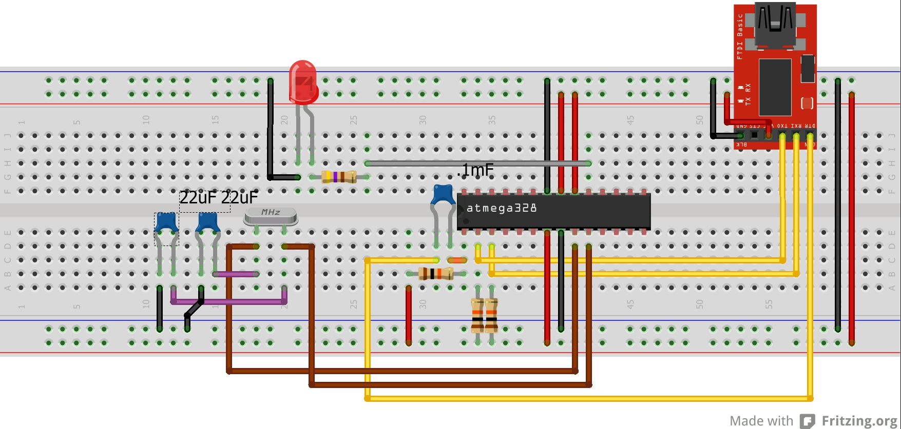
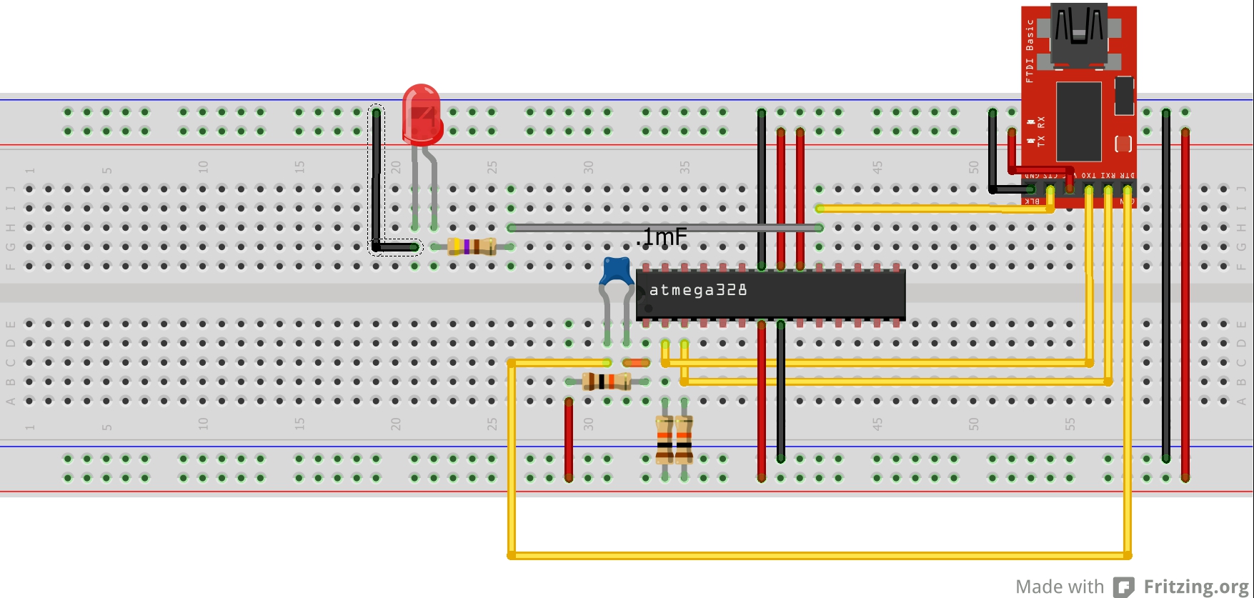
Now for the hardware. In order to completely turn off the servo so that it isn’t drawing unnecessarily on the battery, we need to use a general purpose NPN switching transistor. I used a 2N4401.
From the Arduino: Pin 7 goes to the base of the transistor.
From the transistor emitter: To the power pin of the servo.
From 5 volts: to the collector of the transistor.
From servo ground pin to ground.
What we have done is set a pin in code as an output (tranPin) that we activate right before we tell the servo what to do. This turns the power on to the power pin of the servo. Then when our servo has finished the job set in loop we set the tranPin low. That turns power to the servo back off.
Please comment with questions of head over to our forum to have a discussion.
Join the Forum discussion on this post