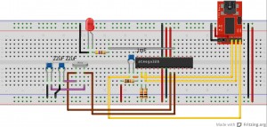
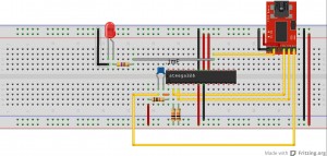
This is if you want to program your breadboard arduino and have an atmega328P-PU with the Optiboot bootloader already on the chip. The biggest issue I have found with breadboarding any chip is that they don’t always want to fully seat into the breadboard. In my experience, I find that pressing firmly down on the chip while uploading saves a ton of trouble!
The LED attached to pin 19 (D13) of the chip is there just as an example. I usually upload the example Blink sketch first to verify that I am able to upload a sketch since it gives me visual confirmation.
If you are using an oscillator.
Note: the caps with the oscillator are pF, NOT uF. Sorry.
If you want to use the FTDI Basic Breakout Board for timing.
Join the Forum discussion on this post


I did what you suggested and it works. So, thanks a lot !. I compared your circuit with the others I found in the Web (probably all older than yours). The main difference are the two resistors of 10KOhm on pins 2 and 3 of the Atmega328P-PU. Is this is due to the PU version of the microchip?