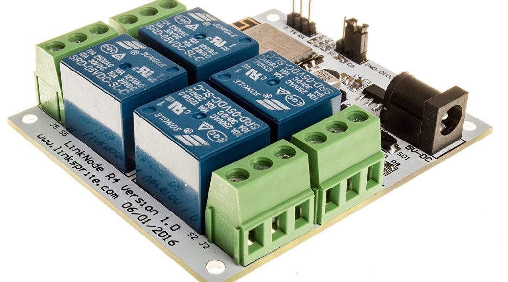
I purchased the LinkNode R4 from amazon because it was cheap, looked fun, and useful. I haven’t really found anything I need to use this for yet but I hope this might help someone else get started with this inexpensive board.
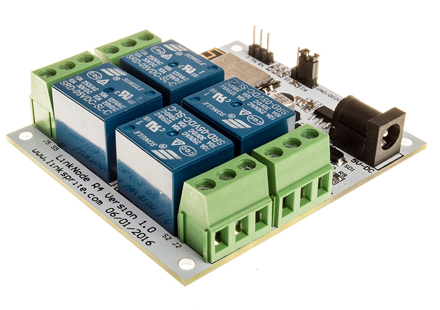
It uses an ESP8266-12F for the controller. This is a very cool little microcontroller. It has 512k of flash, features list from the datasheet:
Features • 802.11 b / g / n • Built Tensilica L106 ultra-low power 32-bit micro MCU, clocked at 80 MHz and supports 160 MHz, support for RTOS • Built-in 10 bit precision ADC • Built-in TCP / IP protocol stack • Built TR switch, balun, LNA, power amplifier and matching network • Built-in PLL, voltage regulator and power management components, 802.11b mode +20 dBm output power The guard interval • A-MPDU, A-MSDU aggregation and 0.4 s of • WiFi @ 2.4 GHz, supports WPA / WPA2 security mode • Supports remote upgrade and cloud AT OTA upgrade • Support STA / AP / STA + AP mode • Support Smart Config function (including Android and iOS devices) • HSPI, UART, I2C, I2S, IR Remote Control, PWM, GPIO • Deep sleep holding current 10 uA, shutdown current of less than 5 uA • Within 2 ms of wake-up, connect and transfer data packets • Standby power consumption is less than 1.0 mW (DTIM3) • Operating temperature range: -40 ℃- 125 ℃
I like to use Cayenne with my IOT devices, so I am writing this with that in mind.
There no assembly required for this board. Just make sure you have a decent power supply. It uses 5 volts but, I used a 5 volt 2000ma supply. You will also need a FTDI chip to flash it, or an arduino. I will cover how to flash it with the FTDI chip.
To make this board ready to program you must put the mode header across the first two pins. 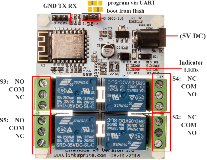
You will also need to apply power to the board to program it. You will not be able to power and flash it with just the FTDI chip.
Wire from the LinkNode to the FTDI TX to RX and RX to TX and GND to GND. Power on the LinkNode then plug in the FTDI to your computer. Open the Arduino IDE 1.6.8 or higher.
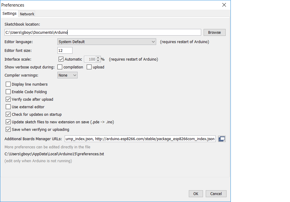
You will need to add the ESP8266 to your boards. To do this click on File-Preferences and add http://arduino.esp8266.com/stable/package_esp8266com_index.json to the Additional Boards Manager URLs section. If you already have other boards here just seperate by a comma.
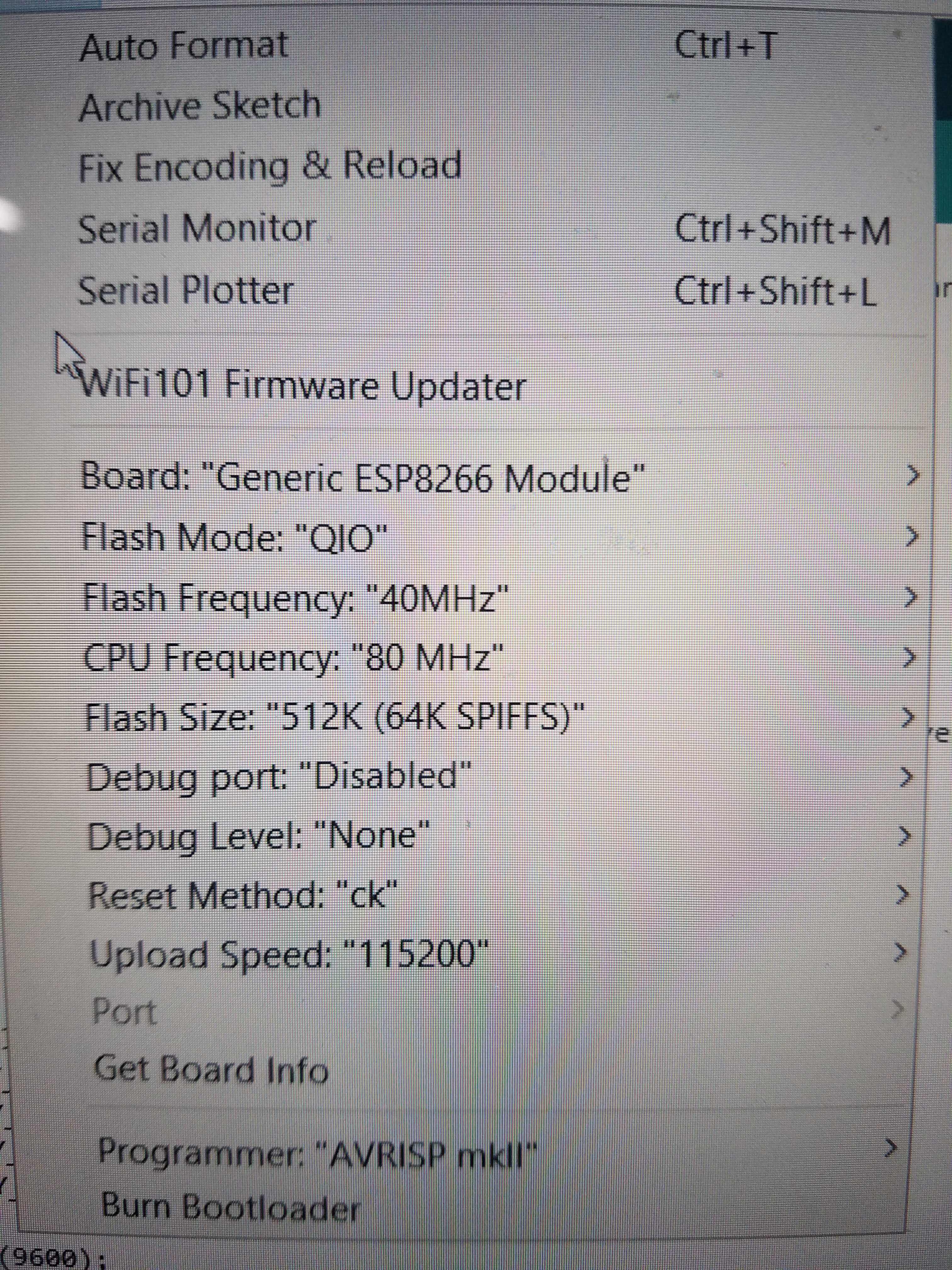
Now you can go to Tools-Board and select Generic ESP8266 Module. Change Flash Mode to QIO.
Now, if you don’t have a Cayenne account, you can create one for free at Cayenne. Continue to your Dashboard and click on Add New-Device-Arduino, and select a board. I chose the Mega but I don’t think it matters. Make a note of your auth token for this device. Now go back to the Arduino IDE and put this code in.
#define CAYENNE_DEBUG // Uncomment to show debug messages
#define CAYENNE_PRINT Serial // Comment this out to disable prints and save space
#include "CayenneDefines.h"
#include "BlynkSimpleEsp8266.h"
#include "CayenneWiFiClient.h"
#define VIRTUAL_PIN 1
#define RELAY_1 12
#define RELAY_2 13
#define RELAY_3 14
#define RELAY_4 16
// Cayenne authentication token. This should be obtained from the Cayenne Dashboard.
char token[] = "your-token";
// Your network name and password.
char ssid[] = "your-wifi-name";
char password[] = "your wifi password";
void setup()
{
// set digital pin to output
pinMode(RELAY_1, OUTPUT);
pinMode(RELAY_2, OUTPUT);
pinMode(RELAY_3, OUTPUT);
pinMode(RELAY_4, OUTPUT);
Serial.begin(9600);
Cayenne.begin(token, ssid, password);
}
// This function will be called every time a Dashboard widget writes a value to Virtual Pin 2.
CAYENNE_IN(V0)
{
CAYENNE_LOG("Got a value: %s", getValue.asStr());
int i = getValue.asInt();
if (i == 0)
{
digitalWrite(RELAY_1, HIGH);
}
else
{
digitalWrite(RELAY_1, LOW);
}
}
CAYENNE_IN(V1)
{
CAYENNE_LOG("Got a value: %s", getValue.asStr());
int i = getValue.asInt();
if (i == 0)
{
digitalWrite(RELAY_2, HIGH);
}
else
{
digitalWrite(RELAY_2, LOW);
}
}
CAYENNE_IN(V2)
{
CAYENNE_LOG("Got a value: %s", getValue.asStr());
int i = getValue.asInt();
if (i == 0)
{
digitalWrite(RELAY_3, HIGH);
}
else
{
digitalWrite(RELAY_3, LOW);
}
}
CAYENNE_IN(V3)
{
CAYENNE_LOG("Got a value: %s", getValue.asStr());
int i = getValue.asInt();
if (i == 0)
{
digitalWrite(RELAY_4, HIGH);
}
else
{
digitalWrite(RELAY_4, LOW);
}
}
void loop()
{
Cayenne.run();
}
You can download the code Here
Make sure to select the COM port for your FTDI chip and click the upload button to flash the LinkNode. If it fails, make sure you have to pin on the program/run header right and reboot the LinkNode, then try again.
Once its flashed, set your Program/run pin to the run position and reboot. You can open the Serial monitor in the Arduino IDE to verify it has connected to Cayenne. Set the baud rate of the Serial Monitor to 9600. Once its connected you can return to Cayenne and click Done. Then Click on New-Widget-Actuator-Relay. Do this four times and make sure to uniquely name each relay so you can differentiate each one. Now you should be able to turn on and off each relay as you wish.
Reference:
LinkNode R4 Wiki
