Disclaimer: Working with mains current is dangerous. Use the information provided in this article/post at your own risk. Always turn off power and confirm no voltage is present on the wires you are going to work with, with a volt meter before beginning work with mains power.
This is an On/Off timer based on the Raspberry Pi. After some really high electric bills I decided I needed to do something to help reduce my burden. The first thing that came to mind that likely runs much more than necessary is the electric water heater. The water heater is designed to constantly retain a certain temperature. However, we only use hot water one to two times daily, once in the morning and again at night.
I needed something that would give me an AM and a PM On/Off schedule. I could have bought a ready made product but I have been looking for a good project for the Raspberry Pi and since it is so much easier to use the Pi for timed projects due to the built in NTP client over the Arduino it was a no brainer.
There are couple of different ways of writing a script to turn on and off the appliance. One way and probably the easiest is to turn on the GPIO pins based on time and then set a delay for the duration you want it on for followed by turning the GPIO pin back off. Another, the way I did it here, is to turn the GPIO pin on and off based on times rather than setting a delay. I feel like making the on and off based on the clock is more elegant and dependable.
Now, on to the Hardware I used and why.
Raspberry Pi (any model) – $35 – Where to purchase
Raspberry Pi case – $8.99 – Where to purchase – This is for the pi B+ or Pi 2. You will need a different case for the other Pi models.
240 volt to 24 volt AC transformer – $14 – Where to purchase
240 volt contactor – $21 – Where to purchase – Steps 240 volts down to 24 volts for the contactor relay.
NPN transistor – $0.12 – Where to purchase – This switches the 24 volt relay.
24 volt relay – $0.64 – Where to purchase – This switches the contactor.
3 position screw down terminal – $0.20 – Where to purchase – 5 volt and grounds terminal block.
2 position screw down terminal – $0.10 – Where to purchase – 24 volt relay terminal for switching the contactor.
Prototyping board – $0.99 – Where to purchase – To solder our components to.
LED (any color) – $0.05 – Where to purchase – To indicate whether the appliance is switched on or off.
Momentary button – $0.25 – Where to purchase – Manual timed on switch
Enclosure – $10.89 – Where to purchase – This is not the enclosure I used but it is the type you should use. Mine is one I had around from Radio Shack.
Wire – $0.00 – You should be able to find appropriate wire laying around. Cat 5 (Ethernet), Cat 3 (Phone Wire), HVAC Thermostat Wire), all will work well for the contactor control board, but just about any wire larger than 24 gauge will be fine. Just make sure that you have a few different colors so you don’t make mistakes by getting confused about what goes where. I use Cat 5 wire because you can find it everywhere these days and because there are 8 differently color coded wires in it.
Wire nuts – $10.96 – Where to purchase – Use wire nuts appropriate for the size of the wire and amount of current.
Wire Terminals – $2.98 – Where to purchase – Use wire terminals appropriate for the size of your wire and amount of current.
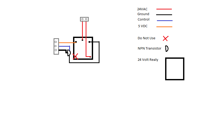
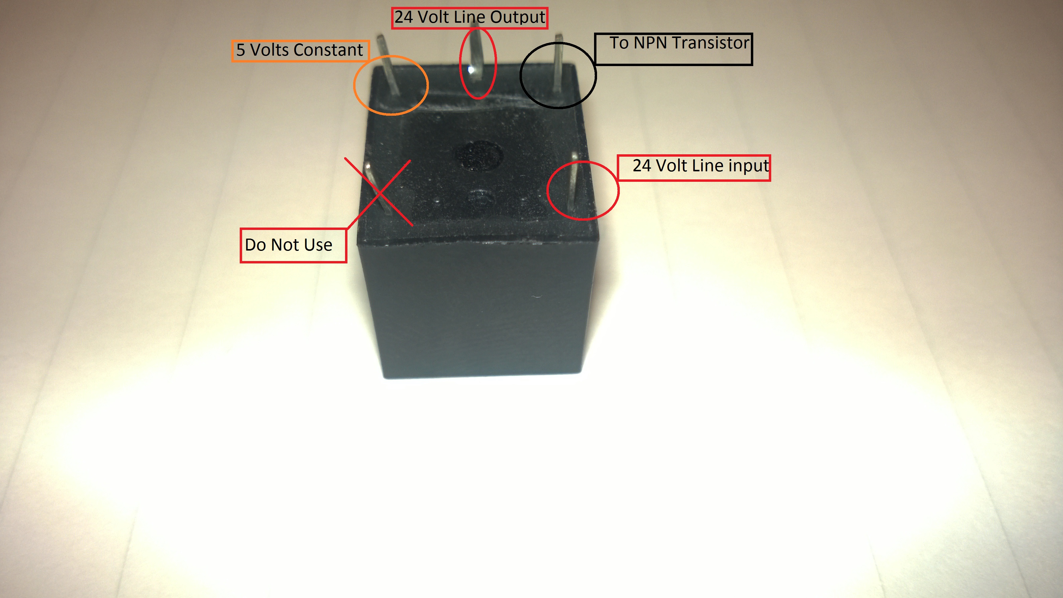
Crude Schematic of Contactor Control Board
Click pictures to show larger view.
These pictures are showing the bottom of the board where the pins come through.
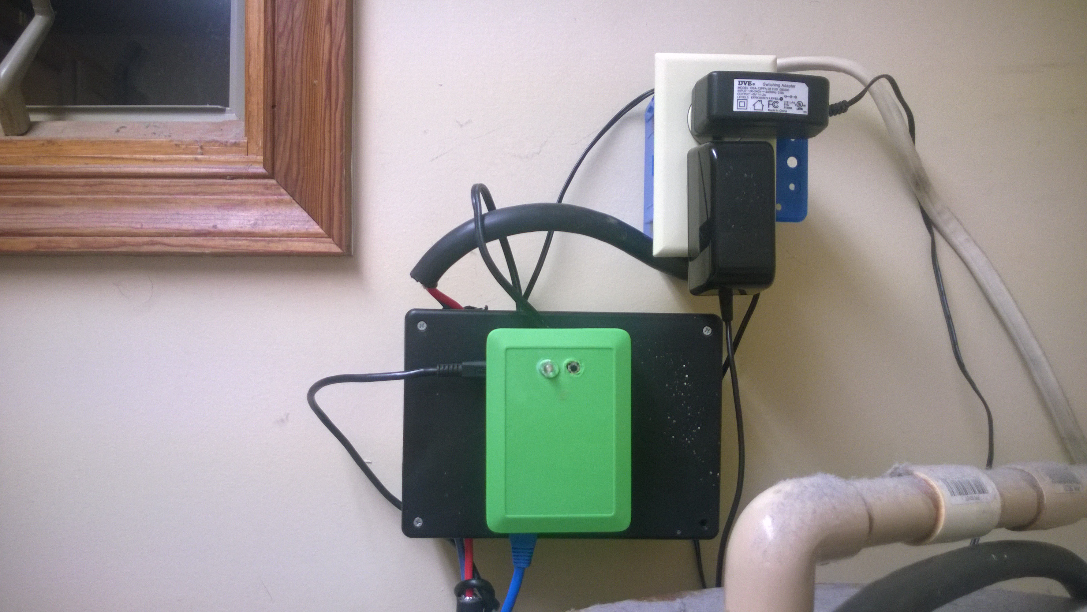
Semi complete Project
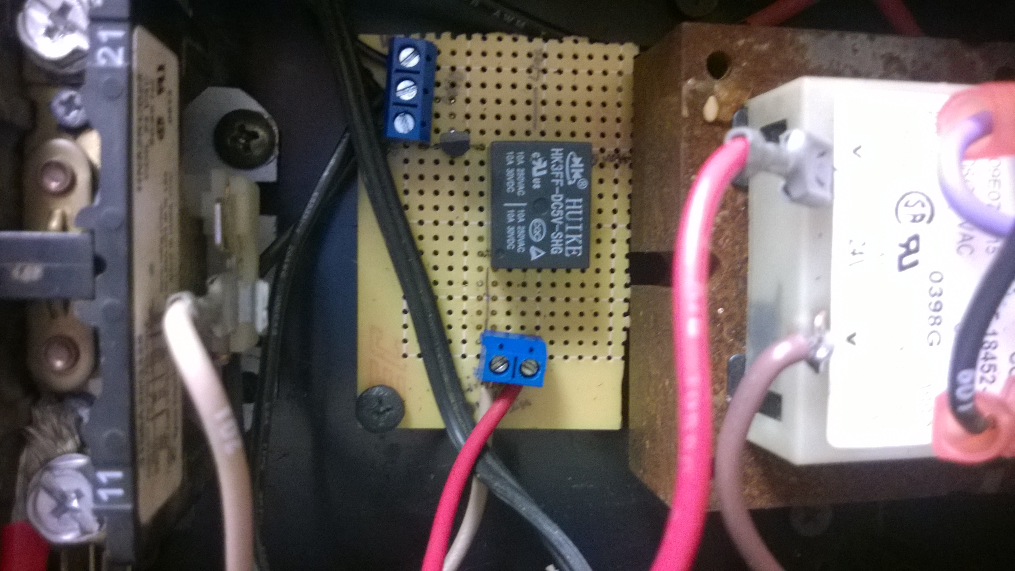
![WP_20150814_004[1]](http://www.modsbyus.com/wp-content/uploads/2015/08/WP_20150814_0041.jpg)
Make the Contactor Control Board
Since the 24 volt relay is the largest component on the controller board, it should be the component you structure the rest of the components around. I placed the transistor close enough to the relay that I was able to solder it directly to the relay pin. You can use wire to connect each point on the board or make solder traces connecting it all together. You should be able to follow my crude schematic to put together the control board, but if you need further instruction please leave a comment or email me at modsbyus ‘at’ modsbyus.com. I will be more than happy to give further assistance.
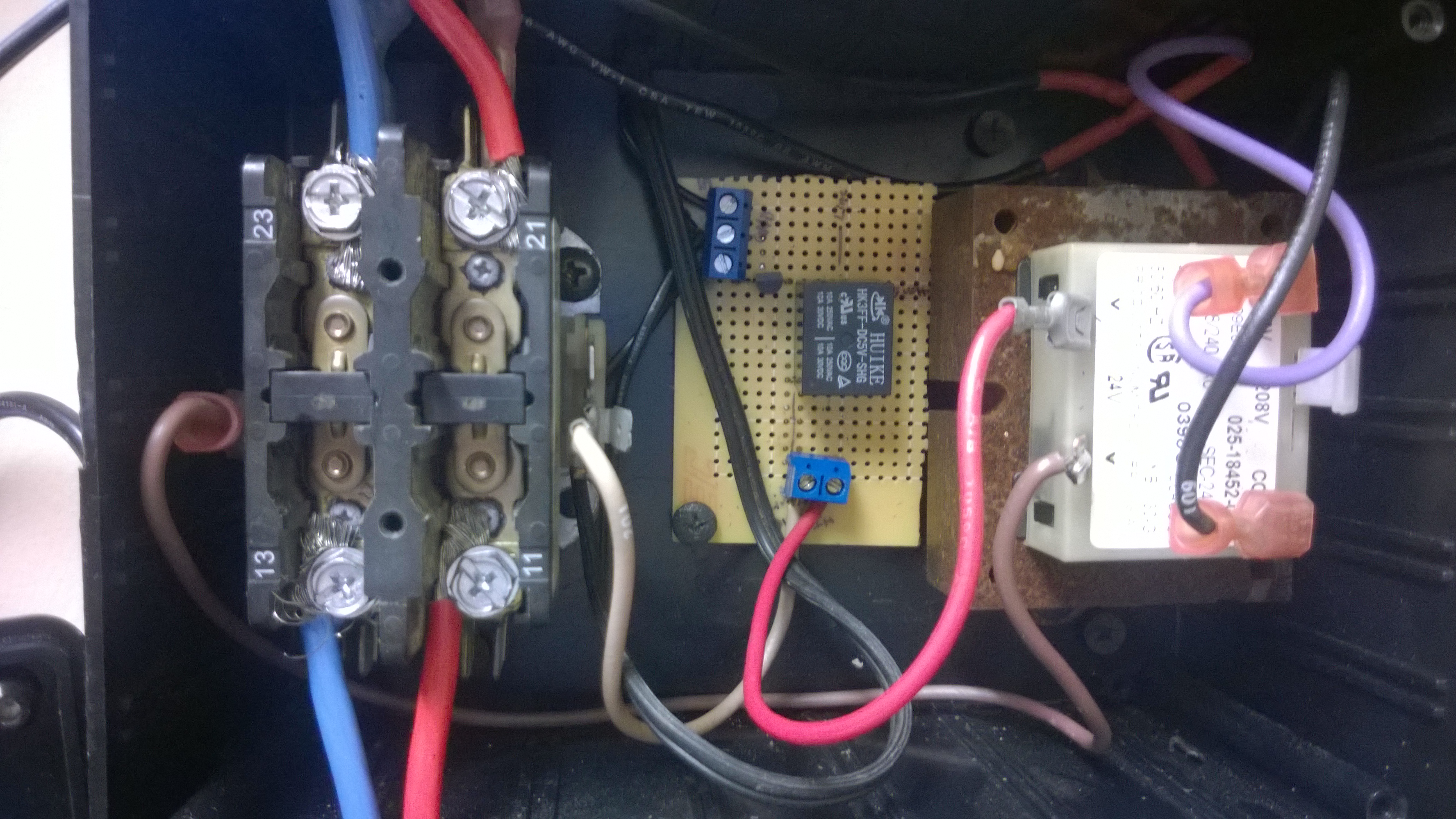
Putting Together The Mains Components
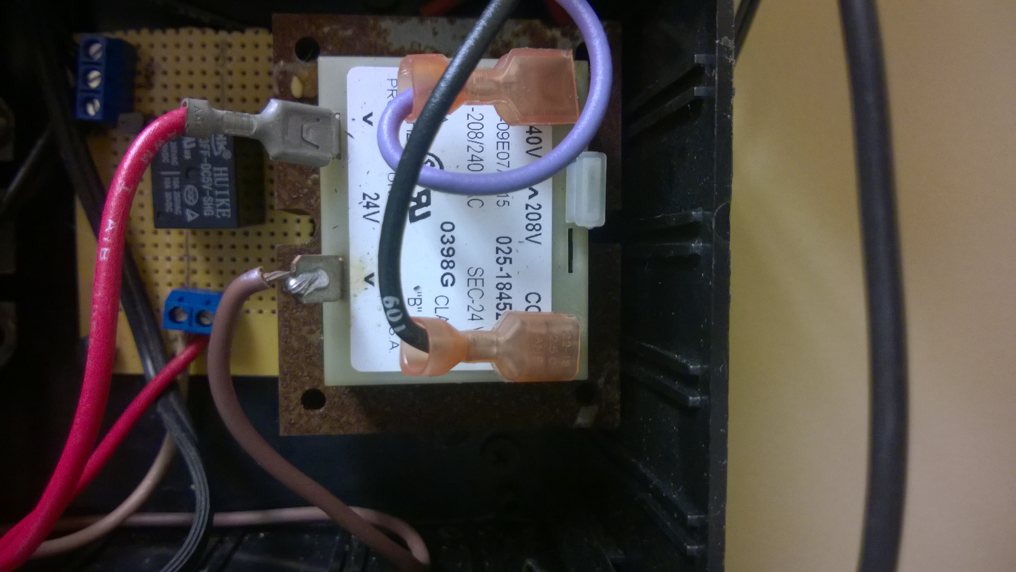
The 240/24 Volt AC Transformer
This transformer has 4 wires for connecting to the mains. The black and white ones are for 120 volts and the orange and red ones are for 240 volts. Use the pair that is appropriate for your usage. The 24 volt wires are blue and yellow.
The yellow wire is going to connect to the relay terminal on the control board and then you make a connection from the other position on the relay terminal to one side of the contactor. The blue wire goes directly to the other side of the contactor.
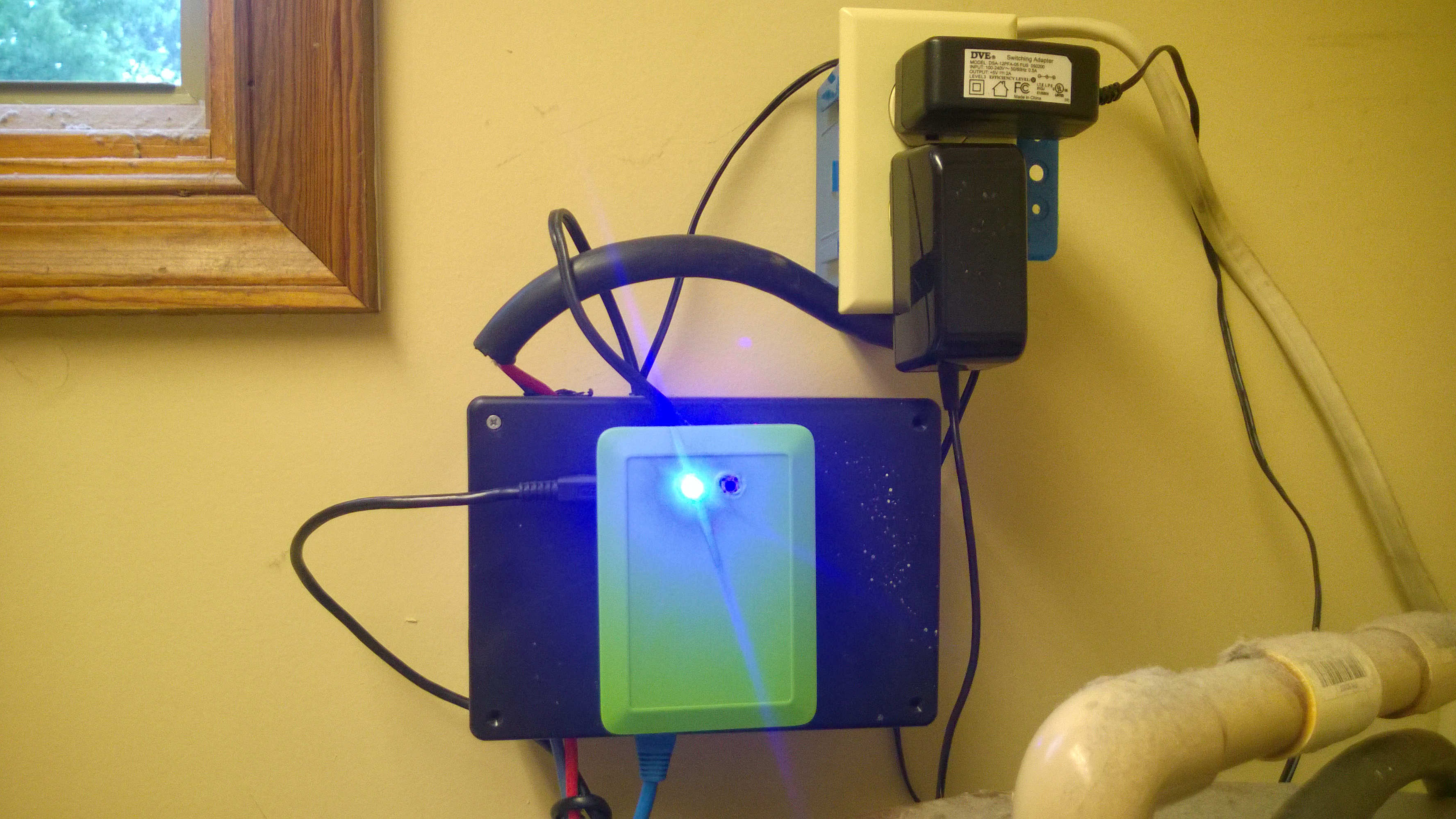
The Enclosure
Depending on the enclosure you choose for your project, mounting will be different. You need to make sure that your Raspberry Pi is mounted in its own case outside of the enclosure for the mains components. The EMD (electro magnetic discharge) from the contactor opening and closing can cause damage to your Raspberry Pi and can also cause unexpected unclean shut downs. You can put the timed override switch and status LED mounted through the enclosure.
The Raspberry Pi
I highly recommend using a Pi case for your Raspberry Pi. It will protect your Pi from all sorts of damage and it looks nicer.
We are going to use GPIO pins 17, 24, and 27 and 3 ground pins.
17 and one ground pin is wired to the timed override switch.
24 and one ground pin is wired to the LED. The long leg of the LED goes to the GPIO 24 pin.
27 goes to the control position on the 3 position terminal block which is connected to pin 1 of the transistor.
A third ground goes to the ground position of the 3 position terminal block which is connected to pin 2 of the transistor.
You will need a constant 5 volt supply for the relay which goes to the 5VDC position of the 3 position terminal block. You can use a 5 volt pin from the Raspberry Pi but I don’t recommend it for this project. Whenever you turn off a coil or motor it sends back high voltage spikes that can damage your Raspberry Pi. I suggest finding a 5 volt power supply to use. The positive line of the 5 volts goes to the 5VDC position of the 3 position terminal block and the ground or negative of the power supply goes to the ground position of the 3 position terminal block.
The Python Program That Runs it
You can download it Download ApplianceTimer.py
# Raspberry Pi custom appliance timer # import GPIO module import RPi.GPIO as GPIO # set up GPIO pins as outputs GPIO.setmode(GPIO.BCM) GPIO.setup(17, GPIO.IN, pull_up_down=GPIO.PUD_UP) # Button GPIO.setup(27, GPIO.OUT) # Appliance 5/25 volt relay GPIO.setup(24, GPIO.OUT)# LED state = 0 button = GPIO.input(17) # import date and time modules import datetime import time # Enter the times you want the appliance to turn on and off for # each day of the week. MonAMOn = datetime.time(hour=5) MonAMOff = datetime.time(hour=7) MonPMOn = datetime.time(hour=16) MonPMOff = datetime.time(hour=22) TueAMOn = datetime.time(hour=5) TueAMOff = datetime.time(hour=7) TuePMOn = datetime.time(hour=16) TuePMOff = datetime.time(hour=22) WedAMOn = datetime.time(hour=5) WedAMOff = datetime.time(hour=7) WedPMOn = datetime.time(hour=16) WedPMOff = datetime.time(hour=22) ThuAMOn = datetime.time(hour=5) ThuAMOff = datetime.time(hour=7) ThuPMOn = datetime.time(hour=16) ThuPMOff = datetime.time(hour=22) FriAMOn = datetime.time(hour=5) FriAMOff = datetime.time(hour=7) FriPMOn = datetime.time(hour=16) FriPMOff = datetime.time(hour=22) SatAMOn = datetime.time(hour=5) SatAMOff = datetime.time(hour=7) SatPMOn = datetime.time(hour=16) SatPMOff = datetime.time(hour=22) SunAMOn = datetime.time(hour=5) SunAMOff = datetime.time(hour=7) SunPMOn = datetime.time(hour=16) SunPMOff = datetime.time(hour=22) # Store these times in an array for easy access later. OnTimeAM = [MonAMOn, TueAMOn, WedAMOn, ThuAMOn, FriAMOn, SatAMOn, SunPMOn] OnTimePM = [MonPMOn, TuePMOn, WedPMOn, ThuPMOn, FriPMOn, SatPMOn, SunPMOn] OffTimeAM = [MonAMOff, TueAMOff, WedAMOff, ThuAMOff, FriAMOff, SatAMOff, SunAMOff] OffTimePM = [MonPMOff, TuePMOff, WedPMOff, ThuPMOff, FriPMOff, SatPMOff, SunAMOff] # Start the loop that will run until you stop the program or turn off your Raspberry Pi. while True: button = GPIO.input(17) #print('ttt') global state if button == 0: #print('button', button) state = 1 #print('state', state) if state == 1: time.sleep(0.5) GPIO.output(24, True) GPIO.output(27, True) time.sleep(3600) #3600 state = 0 GPIO.output(24, False) GPIO.output(27, False) # get the current time in hours, minutes and seconds currTime = datetime.datetime.now() #print(currTime) # get the current day of the week (0=Monday, 1=Tuesday, 2=Wednesday...) currDay = datetime.date.today().weekday() #Check to see if it's time to run the appliance for the AM hours while (currTime.hour >= OnTimeAM[currDay].hour and currTime.hour <= OffTimeAM[currDay].hour): # set the GPIO pin to HIGH GPIO.output(24, True) GPIO.output(27, True) time.sleep(60) currTime = datetime.datetime.now() currDay = datetime.date.today().weekday() else: if (currTime.hour >= OffTimeAM[currDay].hour - 1): GPIO.output(24, False) GPIO.output(27, False) #Check to see if it's time to run the appliance for the PM hours while (currTime.hour >= OnTimePM[currDay].hour and currTime.hour <= OffTimePM[currDay].hour): GPIO.output(24, True) GPIO.output(27, True) time.sleep(60) currDay = datetime.date.today().weekday() currTime = datetime.datetime.now() else: if (currTime.hour >= OffTimePM[currDay].hour - 1): GPIO.output(24, False) GPIO.output(27, False) |
Disconnected Testing
You should run a dry test without the mains connected to the contactor. You don’t want to damage anything or hurt yourself. As long as you can push the override switch and it stays on for the expected amount of time and it comes on and goes off properly for a specified time period then you are good to go.
Bringing it All Together
Its time to hook up the mains (240 or 110 Volts) to the contactor. The feed lines go to one side and the lines to your appliance go to the other side. Use the pictures above as a reference. As always you should follow all safety procedures for dealing with main current and if you don’t know what you are doing then you have no business messing with it. YOU CAN KILL YOURSELF OR OTHERS!
Live Testing
After hooking in the mains and your appliance its time to give it a real test. Set and AM and a PM time for short durations during a time you can monitor it. Turn everything on, boot up the PI, test out the override switch and the timed functions.
Set it and Forget it
The easiest way I have found to set a python script to start when you boot the Pi is to set it as a Cron job using Webmin.
HARDWARE_HACKS has a great tutorial on how to setup Webmin. Follow that then return here for the Cron Job how to.
If you have Webmin setup and you are logged in click on System then Scheduled Cron Jobs
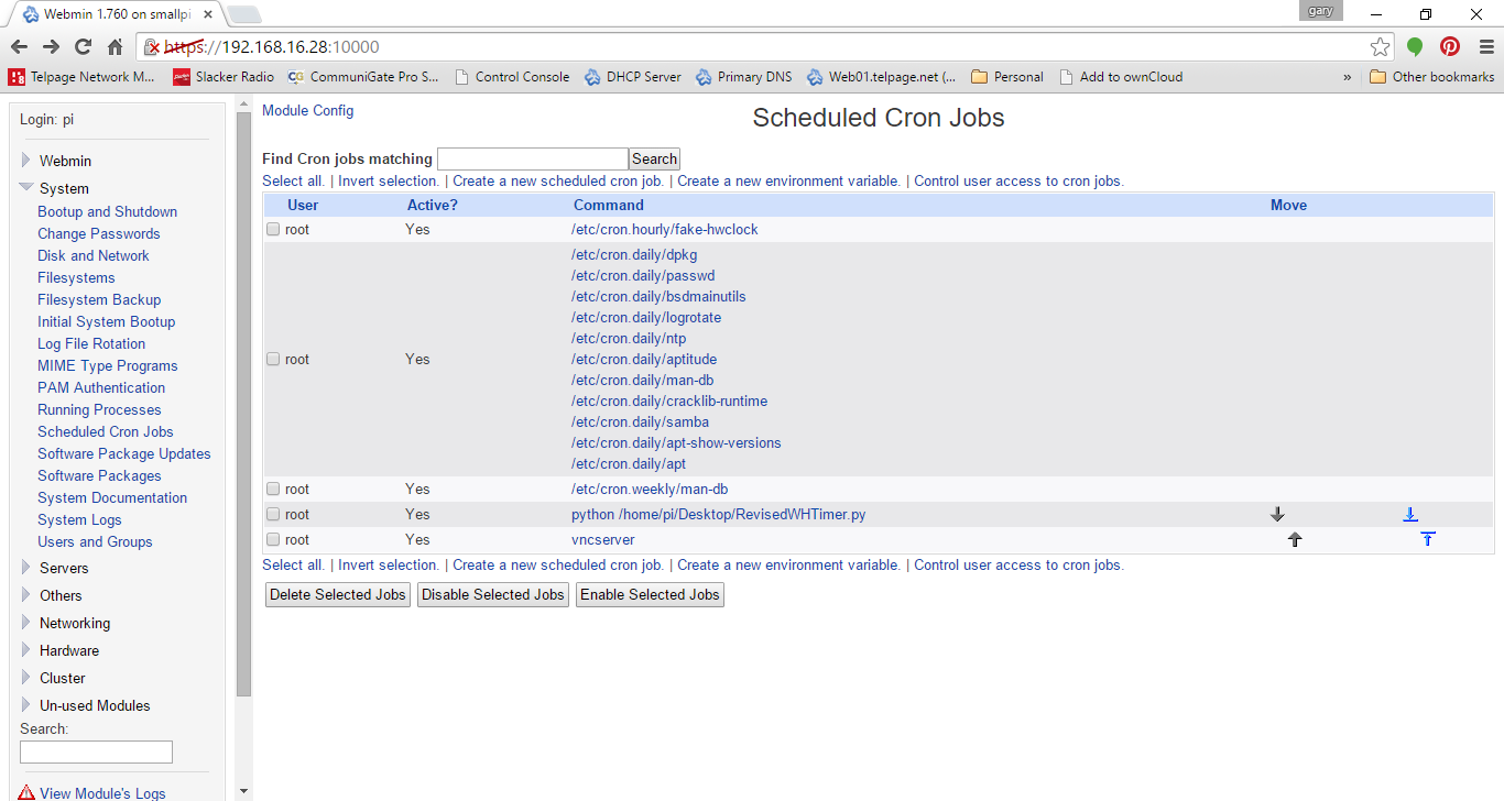
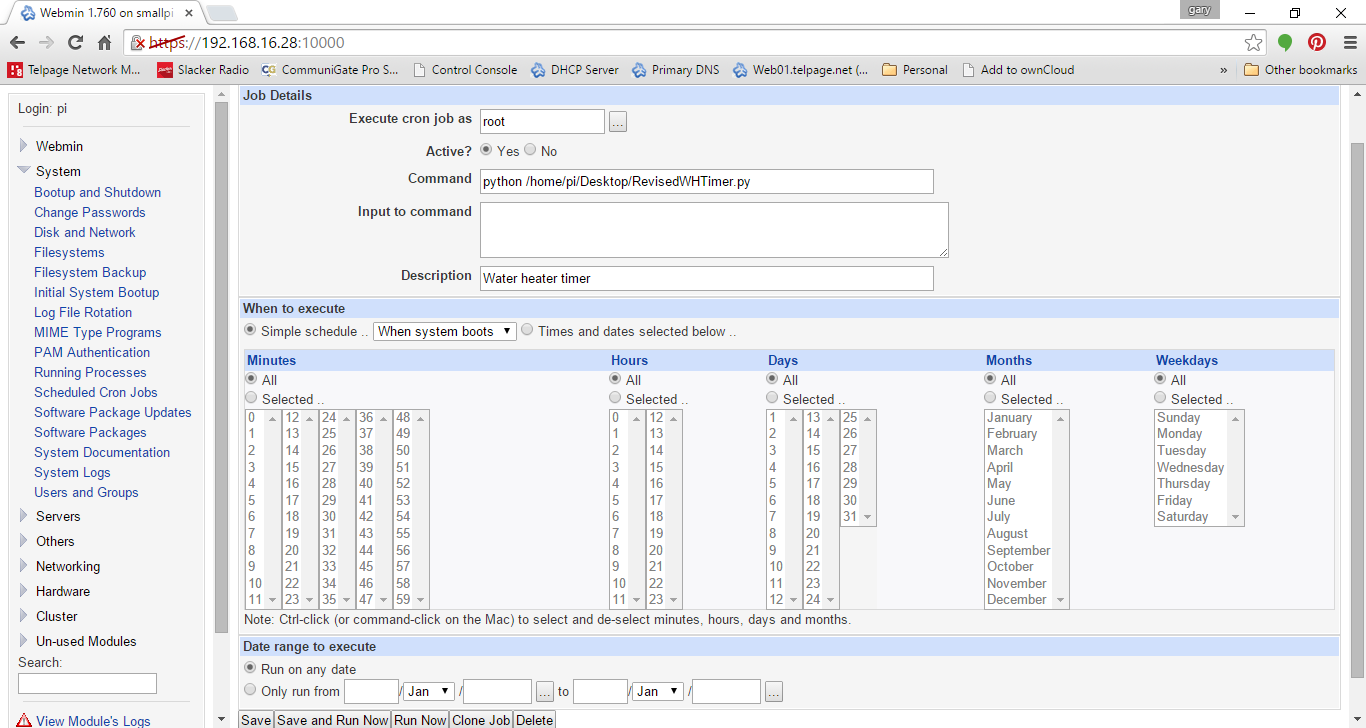
Now click on Create a New Scheduled Cron Job.
It should look like this. The only difference is that for the Command that you put in the path for your python script.
python /home/pi/Desktop/RevisedWHTimer.py
Now Just
sudo reboot
and you are all done! It should come on and go off based on the schedule you set.
Special Note:
The Raspberry Pi does not do well with improper shutdowns. It will cause system corruption. For the sake of all the hard work you just went through, run this on a UPS or some type of reliable battery system.